Electronic voting machines (EVMs) are used to conduct elections in India. These machines provide straightforward and effortless features to voters to cast their votes in favour of candidates of their choice. When a voter presses a button adjacent to the name of the candidate, a beeping sound is made by the EVM, confirming successful casting of vote, and the vote count of that particular candidate increases by one.
In this project, a demo software program using MATLAB based graphical user interface (GUI) to demonstrate the working of an EVM is presented. A screenshot of the EVM using MATLAB GUI is shown in Fig. 1.
Fig. 1: Screenshot of the EVM based on MATLAB GUI
Software Program
Five candidates are considered in this demo program. The GUI application program has been developed in R2014a version of MATLAB.
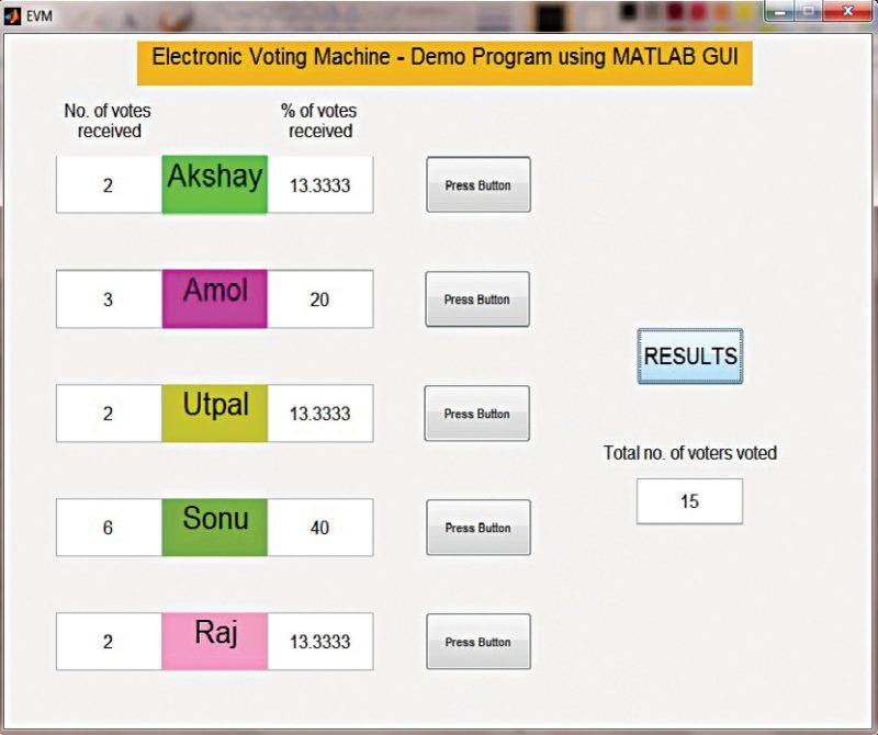
On running MATLAB program (EVM.m), when you select the button marked ‘Press Button’ adjacent to the name of the candidate in the GUI, a beep is heard, confirming successful casting of vote. Selection of the pushbutton executes a callback function in MATLAB, and the candidate’s vote count is incremented by one in the program. At the end of the voting process, the following information can be obtained by selecting ‘RESULTS’ on the GUI:
1. Total number of votes received by a candidate
2. Percentage of votes received by a candidate
3. Total number of voters who have cast their votes
A typical example of the program output screenshot is shown in Fig. 2.
Fig. 2: Program output screenshot with results
Although this article presents a simulation of the working of an EVM, you can build a MATLAB GUI based EVM in hardware like Arduino board. The following pointers might be beneficial:
1. Use pushbutton switches to cast the vote and check results. These pushbuttons can be connected as inputs to the digital input/output pins of the Arduino Uno board.
2. Use Arduino Uno and Legacy MATLAB and Simulink Support for Arduino software package to set up the communication between the Arduino and MATLAB. The procedure to install the package is discussed in detail in ‘Controlling a Robotic Car Through MATLAB GUI’ DIY article. Arduino can send the status of the pushbuttons to MATLAB. Modify the GUI program to perform the tasks as demonstrated by the simulation.
People are often portrayed as the weakest link in a security chain. People can be fooled into revealing passwords, or will often choose passwords that are easily decipherable. It is a misconception that may lead some business owners or IT professionals to believe that IoT, given its near total level of automation, is inherently secure. Nothing could be further from the truth, because nothing is inherently secure.
IoT environments present cyber-criminals with a labyrinth of opportunities, and this year that labyrinth is expected to grow in size by 15 percent (year-on-year) to reach 20 billion devices, according to IHS Markit. To put that figure into perspective, the total number of unique mobile subscriptions globally stands at 4.9 billion (according to the GSMA). IoT dwarfs P2P mobile use in terms of connections and, subsequently, in terms of its potential for breaches in security. (Read More)
Cybersecurity for the Travelling Scientist
Cybersecurity concerns can be particularly acute when crossing international borders. Some regions have a reputation for hacking, and border guards might insist on seeing files.
What can researchers do to keep their data safe from prying eyes on the road? It depends on your data and the threats you’re likely to face, says Morgan Marquis-Boire, director of security for First Look Media in San Francisco, California, who has experience helping government whistle-blowers travel with sensitive data. Are you concerned mostly about overzealous border guards, opportunistic theft or government-sponsored hacking?
Whatever the perceived threat, the first step in data protection, says Marquis-Boire, is encryption — rendering data unreadable by mathematically transforming them with an electronic key. This simple step can protect against casual theft and deter all but the most determined hackers. “The number one thing we push for is encryption of data, whole-disk encryption of portable devices especially,” says John Southall, a data librarian at the University of Oxford,
IoT Products May Soon Require US Government Security Check
A new bill, introduced by members of the US senate, would require stricter government oversight of the the security and manageability of Internet of Things (IoT) devices used by the government.
The bill, brought by a bipartisan group of senators, aims to address some of the glaring security vulnerabilities present in many of these connected devices.
The bill itself was sponsored by four senators—Democrats Mark Warner and Ron Wyden, along with Republicans Cory Gardner and Steve Daines. The bill’s official purpose is stated as “To provide minimal cybersecurity operational standards for Internet-connected devices purchased by Federal agencies, and for other purposes.”
While the regulations would be strict, they’re not hard and fast. Users can apply for a waiver to purchase devices that aren’t compliant with the rules, as long as other precautions are in place, the bill states. (Read More)
Automation is defined as carrying out a set of predefined procedures to achieve a specific outcome. Introduction of engineering automation can be dated back to the time when command-line interfaces (CLIs) were overtaken by graphical user interfaces (GUIs). Automation has passed technical barriers from engineering to medicine to commerce to entertainment.
Automation is necessitated due to the infinite amount of data being spilled over by the information age. Every data set has different specs, requirements, objectives and outcomes. Fig. 1 sheds some light on the various automations embedded in our lives.
Scripting languages like Python, TCL, PHP, Perl and PowerShell are utilised in all fields of engineering. These provide a basis for you to carry out complex tasks easily. These languages are sometimes referred to as very-high-level languages, as these are used to direct various tools and software to work.
Scripting languages are commonly interpretable rather than compilable. Primitive scripting can be seen in the form of Windows batch files (.bat), which run a set of codes sequentially to perform a task from opening MSPaint to shutting down Windows.
Fig. 1: Various automations embedded in our lives
User interfaces inherently use scripts. A simple example to summarise scripts for automation is a single-line batch file as shown in Fig. 2. The file, when executed, copies all .png images from an external device on G:\ to C:\images\ with one click.
In electronics, integrated circuit (IC) designs require scripts to translate designs from one technology to another. An often-used script is Tool Command Language (TCL). Timing analysis, power analysis and floor planning all require scripts to analyse the behaviour of complex circuits being cramped into smaller semiconductor dies to satisfy Gordon Moore’s first law.
Fig. 2: A single-line batch file
Embedded systems use small scripts to embed more functions, thus blurring the barriers between general-purpose systems and application-specific systems—smartphones are the best example of this transition.
With the introduction of the Internet of Things (IoT), embedded systems have entered a new era. Crunching large data (Big Data) provided by millions of IoT devices is a task simplified by Python scripting. Sensors and actuators with networking capability being put on a single board require scripts to operate. MicroPython is an example being utilised by various designers.
In information technology, Python is one of the scripting languages used for carrying out tasks from local machines to servers and the Internet. Perl, PowerShell and other scripting languages help testing and debugging errors from programs. Scripts help automate the process of searching and suggesting solutions for syntax or semantic errors. Data crunching and providing meaningful results is possible with minimal efforts using scripts.
Architectures, structures and buildings are designed using computer-aided technologies like computer-aided design and computer-aided manufacturing tools. Tools like SolidEdge and AutoCad use VBscripts for designs.
In the article ‘Scripting: Higher Level Programming for the 21st Century,’ from IEEE Computer magazine, March 1998 issue, John K. Ousterhout describes how scripting languages glue applications. Interdisciplinary researches require coding, which is indifferent across applications, hence reducing the necessary time to market for products.
Fig. 3 by John K. Ousterhout describes the functionality of different computer languages. In a strongly-typed language, the programmer declares how each piece of information will be used, and the language prevents the information from being used in any other way. Instructions/statements present the number of machine instructions carried out by a particular statement.
Fig. 3: Functionalities of different computer languages
As illustrated in the earlier batch file, scripting languages need not work from scratch for application development as opposed to programming languages that are more suited for dictating algorithms and procedures. A script assumes that useful components are already present in some other language and it has to plug together the components. The IoT, artificial intelligence, machine learning and robotics are spilling new interdisciplinary areas.
Automation snooping into commerce and entertainment is providing better customer experience, which otherwise would be a very tedious task. As quoted by Thomas Devenport and Julia Kirby from ‘Beyond Automation’, Harvard Business Review, June 2015 issue, automation is seen as a concern to human jobs because of the path travelled in the three eras, discussed next.
Three eras of automation
If this wave of automation seems scarier than previous ones, it is for good reason. As machines encroach on decision making, it is hard to see the higher ground to which humans might move.
Era One: 19th century.
Machines take away the dirty and dangerous—industrial equipment, from looms to cotton gin, relieves humans of onerous manual labour.
Era Two: 20th century.
Machines take away the dull—automated interfaces, from airline kiosks to call centres, relieve humans of routine service transactions and clerical chores.
Era Three: 21st century.
Machines take away decisions—intelligent systems, from airfare pricing to IBM’s Watson, make better choices than humans, more reliably and faster.
Developers of 5G radio access technologies, high-end radar systems and automotive applications need a very large bandwidth to analyze wideband signals. A new hardware option for the R&S FSW high-end signal and spectrum analyzer provides 2 GHz analysis bandwidth for these applications.
Rohde & Schwarz is expanding the internal analysis bandwidth of its R&S FSW high-end signal and spectrum analyzer up to 2 GHz by introducing the new R&S FSW-B2001 option. This test solution enables R&D users to investigate wideband signals in detail without the need for an external digitizer.
The R&S FSW-B2001 option provides 14-bit ADC resolution and wide dynamic range, characterized by excellent SFDR figures, for example -65 dBc for 1200 MHz bandwidth. This translates directly into outstanding signal analysis performance. The instrument can measure an EVM of around -40.0 dB error vector magnitude with an OFDM signal (792 MHz BW, 300 kHz spacing, 64QAM, 4096 FFT) at 28 GHz.
Bandwidth up to 2000 MHz facilitates research and development for next generation mobile standards, as well as characterization of wideband amplifiers for 5G. Aerospace and defense developers will be able to use the 2 GHz analysis bandwidth to measure radar pulses down to nanosecond widths, and analyze frequency-agile radar or hopping radio systems. Automotive R&D applications include characterization of FM carrier wave signals for radar applications, and ultrawide bandwidth signals such as those used in keyless entry systems.
The R&S FSW-B2001 option for the R&S FSW43 and R&S FSW50 high-end signal and spectrum analyzers with frequency ranges up to 43.5 GHz and 50 GHz is now available from Rohde & Schwarz. In addition, those R&S FSWs already equipped with 1200 MHz internal analysis bandwidth (option R&S FSW-B1200) are readily upgraded via a key code.
A recent report by Gartner predicts that there will be 20.4 billion connected Internet of Things (IoT) devices by 2020, with 5.5 million new things getting connected every day. Furthermore, more than half of major new business processes and systems will include an IoT component by 2020.
These numbers are staggering and suggest that standard PC security and anti-virus solutions will not be able to counter future cybersecurity threats on connected IoT devices. The need for more robust measures to secure IoT embedded devices was confirmed by recent Forrester’s TechRadar research that defined the use cases, business value, and outlook for the 13 most relevant and important IoT security technologies. This included core technologies, such as IoT authentication and IoT encryption, in addition to emerging IoT security technologies like IoT threat detection, IoT blockchain, and IoT security analytics. (Read More)
Security leaders: Prepare Now for the Convergence of IT, OT and IoT
Is the way we practice security is dependent on context? We have physical security teams. We information security and cybersecurity teams. Sometimes we blend the teams together. As the Internet of Things (IoT) gains steam, we publicly question and even lament the security included there, if at all.For some, security is a silo. For others, security is blended.
Adi Dar, CEO of Cyberbit, points out that attackers don’t care. Dar led Cyberbit since it was spun off from Elbit Systems, Israel’s largest defense contractor and the #26th largest in the world (NASDAQ: ESLT). Prior to that, Dar served as CEO of Elop — one of the world’s leading defense electrooptic technology providers and part of the Elbit Group. Dar noted that attackers adept at finding and slipping through the cracks gain an advantage. Understanding this drives a need for us to develop a more complete and timely picture. It’s a pathway to prepare ourselves and our organizations. (Read More)
Nokia: ISPs and Users Must be Aware of IoT Security
Individual users are typically not directly targeted by these DDoS attacks. Instead, IoT users are most often unwitting enablers when connected devices they own are compromised by malware, then recruited in botnets to launch attacks on service providers and large, cloud-connected enterprises. The Mirai malware exploited security vulnerabilities in CCTV cameras that most users weren’t aware of.
Users must protect themselves and their IoT devices by changing default passwords and regularly updating software/firmware. More professional and industrial IoT users should also monitor IoT device and logs for security-related events. It’s a prime responsibility of IoT device and hub manufacturers to quickly address known security vulnerabilities in their installed base through software patches. But it’s impossible to completely secure billions of IoT devices against malware attacks. (Read More)
The Google Brain team developed a software library to perform machine learning across a range of tasks. Their aim was to cater to the needs of their machine learning systems, those that were capable of building and training neural networks. The software was meant to help such systems detect and decipher patterns and correlations, just like the way human beings learn and reason.
In November 2015, Google released this tool under Apache 2.0 licence, making it open to use and providing everyone an opportunity to work on their own artificial intelligence (AI) based projects. By June 2016, 1500 repositories on GitHub mentioned the software, of which only five were from Google.
The tool under discussion is TensorFlow. What is it about this tool that makes it suitable for machine learning applications? How do you use the tool? Why does Google hold it at such high regard, and why are so many people contributing to it? This article gives you an overview of how TensorFlow flows.
Working with TensorFlow
When you import TensorFlow into Python environment, you get complete access over its classes, methods and symbols. Take TensorFlow operations and arrange these into a graph of nodes called the computational graph. Typically, each node takes tensors as inputs and produces a corresponding output tensor. Values for the nodes get evaluated as and when a session is run. Combine nodes with operations—also nodes in a certain form—to build more complicated computations.
Fig. 1: A fully-configured TensorBoard
Customise and improvise.
To tune this for your machine learning application, you need to construct the model such that it can take arbitrary inputs and deliver outputs accordingly. The way to do this with TensorFlow is to add variables, reflecting trainable parameters. Each of these has a type and an initial value, letting you tune your system to required behaviour.
How do you know if your system is functioning exactly the way you intended it to? Simple, just introduce a loss function. TensorFlow provides optimisers that slowly change each variable so that loss function can be minimised. There are also higher abstractions for common patterns, structures and functionality.
Multiple APIs for easier control
As a new user to any software, it is important to enjoy the experience. TensorFlow is built with that mindset, with the highest-level application program interface (API) tuned for easy learning and usage. With experience, you will learn how to handle the tool, and what modification will result in what kind of change to the entire functionality.
It is then obvious to want to be able to work around the model and have fine levels of control over the same. TensorFlow core API, the lowest-level API, helps you achieve this fine control. Other higher-level APIs are built on top of this very core. Higher the level of the API, the easier it is to perform repetitive tasks and to keep the flow consistent between multiple users.
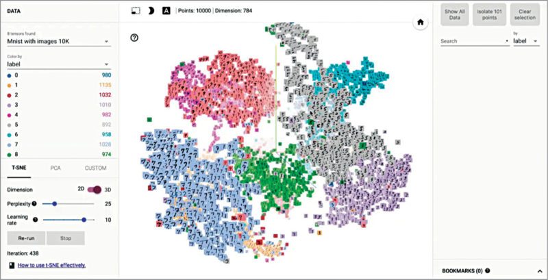
MNIST is ‘Hello World’ to machine learning
Mixed National Institute of Standards and Technology (MNIST) database is the computer vision dataset that is used to train the machine learning system. It is basically a set of handwritten digits that the system has to learn and identify by the corresponding label. Accuracy of your model will depend on the intensity of your training. Broader the training data set, better will be the accuracy of your model.
One example is Softmax Regression model, which exploits the concept of probability to decipher a given image. As every image in MNIST is a handwritten digit between zero and nine, the image you are analysing can be only one of the ten digits. Based on this understanding, the principle of Softmax Regression allots a certain probability of being a particular number, to every image under test.
Smart handling of resources.
As this process might involve a good bit of heavy lifting, just like other compute-heavy operations, TensorFlow offloads the heavy lifting outside Python environment. As the developers describe it, instead of running a single expensive operation independently from Python, TensorFlow lets you describe a graph of interacting operations that run entirely outside Python.
Fig. 2: Embeddings in TensorFlow
A few noteworthy features
Using TensorFlow to train your system comes with a few added benefits.
Visualising learning. No matter what you hear or read, it is only when you visually see something that the concept stays in your mind. The easiest way to understand the computational graph is, of course, to understand it pictorially. A utility called TensorBoard can display this very picture. The representation is very similar to a flow or a block diagram.
Graph visualisation.
Computational graphs are complicated and not easy to view or comprehend. The graph visualisation feature of TensorBoard helps you understand and debug the graphs easily. You can zoom in or out, click on blocks to check their internals, check how data is flowing from one block to another and so on. Name your scopes as clearly as possible in order to visualise better.
A simple homemade oscilloscope that you can use when designing any DIY project. This unit is fairly easy to make just follow the diagram present in the video.
Caution: The max voltage your phone could handle is 3.7 volts and the wave is about 20mV. The software used by presenter in this video is called as AR-Oscilloscope.
In analogue electronics, oscillators and their implementation using integrated circuits (ICs) is an important subject. As 555 timer IC is easy to understand and flexible enough to suit diverse applications, it is used in astable multivibrator (oscillator) configuration for study purpose. While covering the topic in the classroom, instructors often use circuit simulators such as Proteus and TINA to show the output waveform variation of 555 timer IC by changing the resistor or capacitor values.
Fig. 1: The GUI for the 555 timer astable mode simulator
We present here a demo program for a 555 timer-based astable multivibrator, which is implemented using the graphical user interface (GUI) in MATLAB 2014 environment, as shown in Fig. 1. Two resistors and a capacitor are required to operate 555 timer IC in astable mode. When the user enters values of the external components (R1, R2 and C) and presses ‘Run’ button, the simulator provides the time period, frequency and duty cycle of the square wave. The program also shows the output square waveform in the figure window (Fig. 2). The GUI also shows the circuit diagram for operating timer 555 in astable mode.
Fig. 2: Waveform for R1=1000 ohms, R2=1000 ohms and C=1000µF
Software
As mentioned before, 555 timer IC is used in astable mode in order to produce a square wave. Time period (or frequency) and duty cycle of the astable multivibrator is determined by external components R1, R2 and C (refer to the circuit diagram in Fig. 1).
The time during which the output is high:
Th=0.693×(R1+R2)×C seconds
The time during which the output is low:
Tl=0.693×R2×C seconds
Therefore the time period of the square wave is:
T=Th+Tl=0.693×{R1+(2×R2)}× C seconds
and frequency in Hertz (Hz) is:
f=1/T=1.44/{R1+(2×R2)}×C
The duty cycle of the square waveform=Th/(h+Tl)×100%= (Th/T)×100%
The user must enter the values of R1, R2 and C, and click ‘Run’ in order to simulate the astable mode operation of 555 timer IC. On clicking ‘Run’ button, MATLAB executes a callback function to calculate and display the time period, frequency and duty cycle, and plots the waveform. The waveforms for two different sets of component values are shown in Figs 2 and 3, respectively.
Fig. 3: Waveform for R1=1000 ohms, R2=1000 ohms and C=1µF
You can also try out the following by building upon this work:
1. Plot voltage variation across capacitor C
2. Change the supply voltage from 5V to 10V and plot the output waveform; you will find that the amplitude of the output varies
3. Connect a diode (anode to pin 7 of IC and cathode to pin 6) in parallel with R2 and plot the output waveform; you get a 50% duty-cycle output waveform.
Offers excellent AC handling capability and surge robustness for input rectifiers
Beijing, China, August 15, 2017 —Littelfuse, Inc., the global leader in circuit protection, today introduced a series of 16A SCR (silicon-controlled rectifier) switching thyristors developed especially for use in electric vehicle on-board charge (EVOBC) applications. S8016xA Series SCR Switching Thyristors offer excellent AC handling capability and surge robustness, which allows them to handle Level 1 charging up to 16ARMS at 120V, and Level 2 charging up to 16ARMS at 240V at 100°C and up to 25ARMS at 80°C. The S8016xA Series is the first line of SCR switching thyristors capable of handling such high current levels in TO-220R and TO-263 packages that are also AEC-Q101-qualified and capable of supporting the Production Part Approval Process (PPAP).
S8016xA Series SCR Thyristors
Typical applications for S8016xA Series SCR Switching Thyristors are input rectification of AC line inputs for electric vehicle on-board and off-board chargers.
“The compact TO-220R and TO-263 packages in which S8016xA Series SCR Switching Thyristors are provided helps circuit designers minimize the size of their charging circuitry,” said Koichiro Yoshimoto, business development manager for the Littelfuse product line. “As AEC-Q101 qualified devices that are capable of supporting PPAP, they’re ideal for use in EVOBC applications.”
S8016xA Series SCR Switching Thyristors offer these key benefits:
• With a maximum repetitive off-stage voltage (VDRM) of 800V, they can handle inputs from AC mains of up to 250VRMS.
• An RMS on-state current (IT(RMS)) up to 25A makes them suitable for use with Level 1 and Level 2 AC charging applications.
• With a high peak non-repetitive blocking voltage (VDSM) of 1300V and a non-repetitive peak surge current (IPP) of 2400A, they can survive a 6kV surge when used with a proper automotive-qualified metal oxide varistor (MOV) for AC mains overvoltage protection, such as the Littelfuse AUMOV® Series.
• AEC-Q101 qualified and capable of supporting PPAP (production part approval process), making them ideal for protecting a Level 1 AC onboard charger.
Availability
The S8016xA Series is available in either TO-220R packages in quantities of 500, with 50 per tube or in TO 263 (D2-Pak) packaging in quantities of 500 in an embossed carrier reel pack. Sample requests may be placed through authorized Littelfuse distributors worldwide. For a listing of Littelfuse distributors, please visit Littelfuse.com.
MPLAB ICD 4 features a faster processor and increased RAM
16 August 2017, New Delhi, [NASDAQ: MCHP] — Microchip Technology Inc. (NASDAQ: MCHP) today announced the MPLAB ICD 4, an in-circuit programming and debugging development tool for Microchip’s PIC microcontroller and dsPIC® digital signal controller portfolios. The MPLAB ICD 4 includes all the features of the popular MPLAB ICD 3 debugger while adding increased speed through a faster processor and increased RAM.
The MPLAB ICD 4’s significant improvement in speed is accomplished through a 32-bit MCU running at 300 MHz. The faster processing, along with an increased buffer memory of 2 MB, results in a product that is up to twice as fast as its predecessor.
The puck-shaped MPLAB ICD 4 is housed in a durable, black case with a brushed aluminum top and is accented with an LED light strip to indicate debugging status. The tool features the following:
· A wider target voltage range, from 1.20 to 5.5 V
· An optional 1 Amp of power (using an external power supply)
· Selectable pull-up/pull-down option to the target interface
· Configurable interface speed for optimised programming and debugging
· Intelligent, robust interface with fault detection and immunity
· JTAG debugging capability
Microchip’s MPLAB ICD 4 is easy to use and supports all PIC microcontrollers and dsPIC digital signal controllers in Microchip’s portfolio through the MPLAB X Integrated Development Environment (IDE). This simplifies the design process for customers when they choose to migrate from one PIC MCU to another to meet the needs of their application.
“Speed and flexibility are the most important factors when selecting a debugging tool,” said Rodger Richey, Microchip’s director of Development Tools. “The MPLAB ICD 4 reduces wait time—and in turn—improves debugging productivity. With speed, compatibility, durability, comprehensive device support and the award-winning MPLAB X IDE, the MPLAB ICD 4 again solidifies Microchip’s reputation as a leading provider of embedded debugging tools.”
The new family of remote control products use PCI Express Gen 3 technology to help engineers build smarter, faster test systems
INDIA, Bangalore – August 14, 2017: NI (Nasdaq: NATI), the provider of platform-based systems that enable engineers and scientists to solve the world’s greatest engineering challenges, announced today the release of a new family of high-performance PXI remote control and bus extension modules with PCI Express Gen 3 connectivity. PCI Express Gen 3 technology delivers increased bandwidth that is critical for data intensive applications like 5G cellular research, RF record and playback, and high-channel-count data acquisition.
“As technologies converge into smarter devices under test, you increasingly need to build smarter test and measurement systems that leverage the latest processing and data movement capabilities in order to lower the cost of test or improve coverage,” said Luke Schreier, director of automated test marketing at NI. “This new family of remote control modules augments our existing portfolio of PCI Express Gen 3 chassis and embedded controllers and more than doubles the throughput for multichassis systems.”
The PCIe-8398 host interface card communicates over a fully transparent PCI Express Gen 3 x16 link to either the single-port PXIe-8398 or dual-port PXIe-8399 remote control module to offer up to 13.7 GB/s of sustained data throughput. Engineers can use the second port on the PXIe-8399 to daisy chain additional chassis, making it possible to directly interface multiple PXI Express chassis to a single host computer, whether it is a desktop or rack-mount PC.
The PXIe-8394 bus extension module supports peer-to-peer streaming up to 6.8 GB/s between chassis-separated instruments with PCI Express Gen 3 connectivity such as the second-generation vector signal transceiver. In addition to multichassis systems, the PXIe-8394 allows high-throughput communication with peripheral devices like RAID data storage arrays or theATCA-3671 FPGA Module for ATCA. These peripherals typically operate with substantial data sets and can benefit from utilizing the latest PCI Express interfaces.
This new family of PXI remote control and bus extension modules complements the already-released PXIe-8880 embedded controller and PXIe-1085 24 GB/s chassis, both of which also feature PCI Express Gen 3 connectivity. This high-bandwidth portfolio of chassis and controllers is an important part of the NI ecosystem that engineers can use to build smarter test systems. These test systems benefit from more than 600 PXI products ranging from DC to mmWave and feature high-throughput data movement using PCI Express bus interfaces and sub-nanosecond synchronization with integrated timing and triggering. Supported by a vibrant ecosystem of partners, add-on IP and applications engineers, the NI platform helps dramatically lower the cost of test, reduce time to market and future-proof testers for tomorrow’s challenging requirements.
There have been immense and innumerable developments in robotics in recent times—some significant, some not so. Right from form factor and flexibility to motion, sensing and interaction, every aspect of robotics has brought them closer to humans. Robots are now assisting in healthcare centres, schools, hospitals, industries, war fronts, rescue centres, homes and almost everywhere else. We must acknowledge that this has come about not merely due to mechanical developments, but mainly due to the increasing intelligence, or so-called smartness, of robots.
Smartness is a subjective thing. But in the context of robots, we can say that smartness is a robot’s ability to autonomously or semi-autonomously perceive and understand its environment, learn to do things and respond to situations, and mingle safely with humans. This means that it should be able to think and even decide to a certain extent, like we do.
Let us take you through some assorted developments from around the world that are empowering robots with these capabilities.
Understanding by asking questions
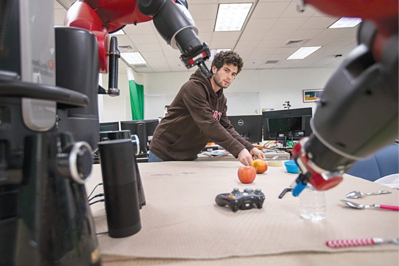
When somebody asks us to fetch something, and we do not really understand which object to fetch or where it is, what do we do? We usually ask questions to zero in on the right object. This is exactly what researchers at Brown University, USA, want their robots to be able to do.
Stefanie Tellex of Humans to Robots Lab of Brown University is using a social approach to improve the accuracy with which robots follow human instructions. The system, called FETCH-POMDP, enables the robots to model their own confusion and solve it by asking relevant questions.
The system can understand gestures, associate these with what the human being is saying and use this to understand instructions better. Only when it is unable to do so does it start asking questions. For example, if you signal at the sink and ask the robot to fetch a bowl, and if there is only one bowl in the sink, it will fetch it without asking any questions. But if it finds more than one bowl there, it might ask questions about the size or colour of the bowl. When testing the system, the researchers expected the robot to respond faster when it had no questions to ask, but it turned out that the intelligent questioning approach managed to be faster and more accurate.
The trials also showed the system to be more intelligent than it was expected to be, because it could even understand complex instructions with lots of prepositions. For example, it could respond accurately when somebody said, “Hand me the spoon to the left of the bowl.” Although such complex phrases were not built into the language model, the robot was able to use intelligent social feedback to figure out the instruction.
Robot asks questions to clarify confusing instructions (Image courtesy: Brown University)
Learning gets deeper and smaller than you thought
Deep learning is an artificial intelligence (AI) technology that is pervading all streams of life ranging from banking to baking. A deep learning system essentially uses neural networks, modelled after the human brain, to learn by itself just like a human child does. It is made of multi-layered deep neural networks that mimic the activities of the layers of neurons in the neocortex. Each layer tries to understand something more than the previous layer, thereby developing a deeper understanding of things. The resulting system is self-learning, which means that it is not restricted by what it has been taught to do. It can react according to the situation and even make decisions by itself.
Deep learning is obviously a very useful tech for robots, too. However, it usually requires large memory banks and runs on huge servers powered by advanced graphics processing units (GPUs). If only deep learning could be achieved in a form factor small enough to embed in a robot!
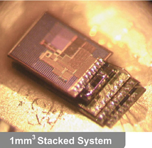
Micromotes developed at University of Michigan, USA, could be the answer to this challenge. Measuring one cubic millimetre, the micromotes developed by David Blaauw and his colleague Dennis Sylvester are amongst the world’s smallest computers. The duo has developed different variants of micromotes, including smart sensors and radios. Amongst these is a micromote that incorporates a deep learning processor, which can operate a neural network using just 288 microwatts.
There have been earlier attempts to reduce the size and power demands of deep learning using dedicated hardware specially designed to run these algorithms. But so far, nobody has managed to use less than 50 milliwatts of power and the size too has never been this small. Blaauw and team managed to achieve deep learning on a micromote by redesigning the chip architecture, with tweaks such as situating four processing elements within the memory (SRAM) to minimise data movement.
Tiny micromotes developed at University of Michigan can incorporate deep learning processors in them (Image courtesy: University of Michigan)
The team’s intention was to bring deep learning to the Internet of Things (IoT), so we can have devices like security cameras with onboard deep learning processors that can instantly differentiate between a branch and a thief lurking on the tree. But the same technology can be very useful for robots, too.
Q. How important is the Indian market for ST and what are the possible MEMS trends you see?
Vishal Goyal, Senior Manager – Technical Marketing, Analog and MEMS Group, RF, Sensors and Analog Custom Products, India, Asean and ANZ, STMicroelectronics
A. According to Gartner, MEMS-based smart sensors are set to gain maximum traction in the worldwide smart sensor market that is forecast to grow to $57.77 billion by 2022; at 18.1% CAGR. The market is driven by factors including concern toward security & surveillance, rising need for energy-efficient devices, growing consumer electronics sector, surge in automotive industry on a global basis, favorable government initiatives, and growing trend of miniaturization in sensors.
MEMS in India is at its starting point and seen massive growth in mobile phones. MEMS is also a key pillar in IoT applications. MEMS sensors like Accelerometers and Gyroscopes, as well as Humidity and Temperature sensors are widely used in IoT applications. A few use cases include Home Automation, Smart City, and Smart Industry. Sensor data will also enable a wide range of cloud services
Q. The IoT is a very big concept which covers a lot of segments. Which segments are ST mainly focused on?
A. Our IoT strategic focus addresses Smart Industry, Smart Home, Smart City and Smart Things. Smart Industry can bring safer and more efficient manufacturing. The philosophy of the Smart City is to share resources better. The Smart Home will improve our quality of life and our security. Smart Things can bring innovative cost-saving solutions for healthcare.
Q. What is your growth perspective for Indian MEMS industry?
A. STMicroelectronics has partnered with many Indian companies and have been working with some of them for two years and now their products are being sold in Europe and USA markets. We hope more and more customers can know MEMS better.
STMicroelectronics globally has huge experience in promotion of MEMS products and we also have had great success in embedded systems. We have developed a kit, development tools and software that help develop embedded systems with MEMS and the full portfolio of ST products. The growth in consumer electronic products alongside the introduction of the sensors in the automotive and medical segments ensures stable growth and the continuing expansion of the MEMS sensors market.
Q. Talk about ST’s latest products displayed
A. i) SensorTile connectable sensor node: plug or solder
Description
STEVAL-STLCS01V1 (SensorTile) is a highly integrated reference design that can be plugged into form-factor prototypes, adding sensing and connectivity capabilities to new designs through a smart hub solution. It can also easily support development of monitoring and tracking applications like standalone sensor nodes connected to iOS™ or Android™ smartphone applications.
The SensorTile occupies a very small 13.5 x 13.5 mm square outline, with all the electronic components on the top side and a small connector on the bottom side to plug it onto the cradle expansion board. The connector pinout is repeated on 18 PCB pads to render the SensorTile a solderable system on module as well.
Features
o Very compact module for motion, audio, environmental sensing and Bluetooth low
energy connectivity with a complete set of firmware examples
o Mobile connectivity via the ST BlueMS app, available for iOS and Android
Main components
o STM32L476 – 32-bit ultra-low-power MCU with Cortex M4F
o LSM6DSM – iNEMO inertial module:3D accelerometer and 3D gyroscope
o LSM303AGR – Ultra-compact high performance eCompass module: ultralow
o power 3D accelerometer and 3D magnetometer
o LPS22HB – MEMS nano pressure sensor: 260-1260 hPa absolute digital
o output barometer
o MP34DT04 – 64 dB SNR digital MEMS microphone
o BlueNRG-MS – Bluetooth low energy network processor
o BALF-NRG-01D3 – 50 Ω balun with integrated harmonic filter
o LD39115J18R – 150 mA low quiescent current low noise LDO 1.8 V
o 2 V – 5.5 V power supply range External interfaces: UART, SPI, SAI (serial
o audio interface), I²C, DFSDM, USB OTG, ADC, GPIOs
o Pluggable or solderable interface
o SWD interface for debugging and programming capability
o RoHS complian
ii) SandPuppy FITBELT
Description:
SandPuppy FITBELT is a smartphone-controlled, pain relief device with a deep, penetrating heat and micro-vibration for on-the-move back-pain relief. The device embeds ST’s low-power microcontroller (STM32L0), Bluetooth™ low energy (BLE) network processor (BlueNRG-MS), and a high-side driver (VN5012AK-E).
ST product inside:
o Micro-controller: STM32L051C8T6
o Access line ultra-low-power 32-bit MCU ARM®-based Cortex®-Mo+,up to 64 KB Flash, 8 KB SRAM, 2 KB EEPROM, ADC
o Bluetooth: BlueNRG-MS
o The BlueNRG-MS is a very low power Bluetooth low energy (BLE) single-mode network processor, compliant with Bluetooth specification v4.1
o High Side Driver: VN5012AK-E
Features
o Portability – Use it wherever you go, while working, in your car or in flight
o Heating – Deep warmth with temperatures adjustable up to 60 degrees Celsius
o Micro Vibration – Adjustable vibration levels to add a soothing hum and melt away the pain
o Smart – Customize heat and vibration levels on a user friendly SandPuppy app
o Fitbelt Dimensions : Length – 45″ Width – 6.75″ Height – 0.5″ to 1″
o Comes with its own charger, mobile app, travel pouch and size extender
o Conceptualized, designed and assembled this product in India by Afferent Wearable Tech Private Limited
ESP32 is a single chip 2.4 GHz Wi-Fi and Bluetooth combo chip designed with TSMC ultra low power 40 nm technology. It is designed and optimized for the best power performance, RF performance, robustness, versatility, features and reliability, for a wide variety of applications, and different power profiles.
ESP32 is designed for mobile, wearable electronics, and Internet of Things (IoT) applications. It has many features of the state-of-the-art low power chips, including fine resolution clock gating, power modes, and dynamic power scaling.
For instance, in a low-power IoT sensor hub application scenario, ESP32 is woken up periodically and only when a specified condition is detected; low duty cycle is used to minimize the amount of energy that the chip expends. The output power of the power amplifier is also adjustable to achieve an optimal trade off between communication range, data rate and power consumption.
Brea, California, August 9th, 2017—Moxa’s MGate protocol gateways offer a built-in set of powerful troubleshooting tools that eases troubleshooting.
Quick and efficient troubleshooting is essential because unpredictable adverse events in a network often result in production and financial losses. When dealing with an issue in a serial-to-Ethernet gateway topology, engineers have to consider troubleshooting both Ethernet and serial protocols. However, while open-source tools are easily available for Ethernet troubleshooting, serial-based protocol troubleshooting lacks such helpful tools. As a result, serial protocol troubleshooting can prove to be a formidable task, frustrating engineers immensely as they waste a substantial amount of time and effort to pinpoint the root cause. Engineers need to find a solution by trial and error, as they don’t have any specific guidelines to follow. Thus, they often find themselves in a dead end.
To address this issue, Moxa’s MGate protocol gateways are enhanced with built-in troubleshooting tools. These tools can range from a communication analysis tool to a protocol diagnostics tool and a traffic monitoring tool. These tools help complete the whole troubleshooting process by locating the issue in a network, checking the status of protocol connections, and monitoring traffic logs to track records.
Most laboratories and educational institutions are in need of precision stopwatch for accurate time measurement. This simple DIY project focuses on the construction of a stopwatch with 0.01-second accuracy. The stopwatch can be used for sports events by connecting a sensor across connector CON2.
Stopwatch circuit and working
The circuit diagram of the precision stopwatch is shown in Fig. 1. It is built around 7805 voltage regulator (IC1), AT89C4051 microcontroller (IC2), 4-digit common-anode 7-segment display (DIS1) and a few other components.
Fig. 1: Circuit diagram of the precision stopwatch
The circuit is powered from 230V AC mains via step-down transformer X1 (not shown here). X1 output (7.5V-0-7.5V AC) is rectified by diodes D1 and D2 and smoothened by capacitors C1 and C4.
Rectified DC voltage is regulated to 5V by 7805 and fed to the microcontroller circuit. The controller (IC2) runs at an oscillator frequency of 12MHz. This is achieved by connecting a 12MHz crystal across XTAL1 and XTAL2 pins of IC2.
Switch S1 is the power on/off switch for the circuit. Capacitors C2 and C3 are used for suppressing high-frequency signals generated by IC1. Capacitors C6 and C7 are decoupling capacitors for crystal. Capacitor C5, and resistor R8 forms a part of power-on reset circuit for IC2.
Switch S2 is used as manual reset for IC2 and to reset the counter to zero. S3 is used to start and stop the stopwatch. A 4-digit multiplexed 7-segment display is used for hardware simplicity and economic benefits. Fig. 2 shows pin details of the 4-digit common-anode 7-segment display.
Fig. 2: Pin details of 4-digit, 7-segment display
When S1 is closed, DIS1 indicates 00.00. On pressing S3, DIS1 starts counting up until S3 is released. DIS1 indicates the last count value till S2 is pressed. Maximum count given by DIS1 is 99.99 seconds.
Software
The software (stopwatch.c) is written in C language and compiled using Keil µVision V5 software. Delay in C language depends on the compiler. Sometimes, a small correction may be required on the delay loop for calibration purpose.
The hex code generated by Keil software is burnt into the microcontroller using a suitable programmer. A Topview Programmer was used for programming the microcontroller during testing. You can use any suitable software for programming the microcontroller.
An actual-size, single-side PCB layout for the precision stopwatch is shown in Fig. 3 and its components layout in Fig. 4.
Fig. 3: PCB layout of the precision stopwatchFig. 4: Components layout of the PCB
Download PCB and component layout PDFs: click here
After assembling the circuit on the PCB, cross-check for any wrong connections. After burning the hex code into AT89C4051, place it on the PCB using an IC base. Fit the PCB, switches, connectors and DIS1 in a general-purpose cabinet.
Switch on the unit by closing S1. Ensure that DIS1 shows 00.00 reading. If not, check the circuit for any mistake(s). When you close S3, the display starts counting—open S3 and the counting stops.
If S3 is closed again, the display starts counting from the last count value. Compare the reading with a calibrated stopwatch. If there is a mismatch in the reading, adjust the delay loop in the code till exact timing is attained. At any time, press S2 momentarily to reset the display.
For a simple application, calibration may not be necessary, but for laboratory use, it is recommended to calibrate the unit.
CON2 is provided for replacing S3 with an external switch or sensor.
Engineers often search for lightweight software that has an intuitive interface, fewer components, and models for ease of design and saving time. When designing a faster prototype within limited time, idealCircuit design tool allows you to design schematics and simulate these for specialised applications. While it was initially used for designing power supplies, today it works along NL5 analogue electronic circuit simulator on ideal and piecewise-linear components. This software lets you evaluate and simulate the exact same schematics you see in textbooks.
DesignLab is equipped with functionalities, and you can see your projects lift off the ground in no time. It works on Windows and Linux operating systems and is supercharged by adding circuits. This helps you push your projects into production through faster design creation. Like all integrated development environments (IDEs), Papilio DesignLab lets you develop a hardware description language by typing the code into the IDE, which, in turn, generates a file that is loaded into the field-programmable gate array. Papilio IDE includes a text editor, libraries, revision control, syntax highlighting and a compiler. The unique selling point is the drag-and-drop interface for designing field-programmable gate arrays using Arduino IDE. The tool is limited to Papilio boards only.
PCB123 helps you take advantage of all enhanced user controls for faster rendering, smoother drag and drop, more zoom control and unified control panels while designing PCB boards. The upgraded version included in this month’s DVD lets you access a fully-defined set of parts library, with over 500,000 parts with schematic symbols, footprints, manufacturer and digi-key ordering information and links to data sheets.
IGX SCADA is your answer to how modern SCADA software works. Watching over your factory floor round the clock, this software intelligently tracks and sends out emails and SMSes based on hierarchy and access levels. The software runs and links smoothly to any modern Web browser to provide a bird’s eye view on supervisory control. Its reporting system is very real-time, and presentation of production or monitoring data is built in a comprehensive mathematic functionality to increase accuracy of readings. It decreases downtime and increases productivity with multi-level role based supervision and trackable event based audit trail.
In the race to create artificial intelligence, OpenCog finds itself as the most unique and ambitious open source project that aims to impart intelligence to machines. You can join the community and develop codes and software applications that are at par with or beyond human intelligence. Prime areas of focus are the practical applications used for interacting with humans such as natural language processing and speech.
This utility software is created as an operating system to be operated in large clusters of servers-supporting Cloud. It is based on open source Linux containers and supports container systems out-of-the-box. CoreOS has been designed to produce, maintain and utilise open source software for Linux containers and distributed systems. If you are a computer engineer and researcher who likes programming and providing solutions on Cloud based applications while you make use of emulator, debugger and flash programming utilities, this software is for you.
Though development and use of invisibility cloaks may not have been possible till now for large-scale objects, the technology towards invisibility based on the exotic properties exhibited by meta-materials is now well understood by scientists, engineers and technologists. So we are no longer unaware of the use of invisibility in electronics.
As components on computer chips get smaller, we have to come up with strategies to control electron transport, and use of invisibility characteristics of materials in electronics might be one useful approach. The concept could also lead to a new kind of switches for electronic devices. The switch could operate by toggling between transparent and opaque states of electrons, thus turning a flow of these on and off. This article briefly summarises the developments towards the applications of the concept of cloaking to the domain of electrons that is giving rise to more useful, efficient, smart and lightweight electronic devices. The new invisibility cloak combines meta-materials and leads fancy electronics to be thinner, lighter and invisible.
Fig. 1: What meta-material looks like
Invisibility fundamentals
The last few years have seen a lot of research in invisibility cloaks. These cloaks are mostly based on meta-materials—special, man-made materials that bend radiation in ways that should not technically be possible—allowing for cloaking devices that bend radiation around an object, hiding it from view.
The problem with these cloaks is that meta-materials are tuned to a very specific frequency. So while that specific frequency passes around the object, every other frequency scatters off the cloaks.
In a beautiful twist of irony, most invisibility cloaks actually create more scattered light, making the cloaked object stand out more than if it was just standing there uncloaked. This is a fundamental issue of passive invisibility cloaks, and the only way to get around it is to use cloaks fashioned out of active, electrically-active materials.
This might change in the future with more advanced passive meta-materials, but for now, active designs are the way forward. Research into active invisibility cloaks is currently being carried out by multiple research groups all over the world, but none have yet been built.
Invisibility cloaks are supposed to hide things by bending light around these that would not allow any to be reflected back at a potential viewer, which would allow the invisible thing to be seen.
Invisibility cloaks, which are very successful in movies and are so close to being successful in labs, have a crucial weakness. These make things invisible to the perception of the audience their creators had in mind.
Previous work on cloaking objects from view has relied on so-called meta-materials made of artificial materials with unusual properties. The composite structures used for cloaking cause light beams to bend around an object and then meet on the other side, resuming their original path, making the object appear invisible.
The great unappreciated weakness of invisibility cloaks is that these only make things invisible to human eyes. A cloak made to hide things from humans would be able to bend all colours of visible light, but might not be able to do the same with waves of heat or sound.
It has never been clear whether it was even theoretically possible to make an invisibility cloak that could hide the same object from light, heat and sound. The problem is not just that the cloak material has to bend light, but that it has to have an effect on the light, powerful enough to change its behaviour in very specific ways.
A mirror can change the behaviour direction of a beam of light dramatically, and can hide a person standing behind it, for example, but does not do those things with enough subtlety to convince anyone that it is not there. An advanced meta-material from the category of meta-materials often used in attempts at invisibility might have a powerful, innate ability to scatter light, but could melt when exposed to a lot of heat, or catch fire when in contact with electricity.
Researchers have addressed the need for a material that could manipulate more than one type of material by making a cloak out of two different layers of material with different properties, but each has to be able to shield the other from view within its own slice of the energy spectrum.
A team of researchers has built a double layer of material as a cloak that can keep objects from being seen using either heat or electricity as a viewing medium, using a layer of silicon that attracts and concentrates both electrical current and heat flow, and an inner layer that is actually an empty cavity that scatters both current and heat away from itself. So when an object is placed within the invisibility zone, heat and electricity are diverted around it and scattered around the inside of the cavity. The outer shell then pulls both heat and electricity towards itself, removing the means of being seen from the neighbourhood of the object being hidden.
In this project, the presenter will show you how to create a simple circuit that can interrupt the current flow to a load when the adjusted current limit is reached. That means the circuit can act as an overcurrent or short circuit protection.
 Electronic voting machines (EVMs) are used to conduct elections in India. These machines provide straightforward and effortless features to voters to cast their votes in favour of candidates of their choice. When a voter presses a button adjacent to the name of the candidate, a beeping sound is made by the EVM, confirming successful casting of vote, and the vote count of that particular candidate increases by one.
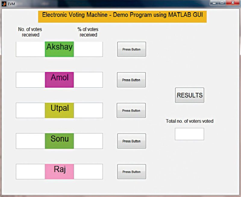
 People are often portrayed as the weakest link in a security chain. People can be fooled into revealing passwords, or will often choose passwords that are easily decipherable. It is a misconception that may lead some business owners or IT professionals to believe that IoT, given its near total level of automation, is inherently secure. Nothing could be further from the truth, because nothing is inherently secure.
 A new bill, introduced by members of the US senate, would require stricter government oversight of the the security and manageability of Internet of Things (IoT) devices used by the government.


 A recent report by Gartner predicts that there will be 20.4 billion connected Internet of Things (IoT) devices by 2020, with 5.5 million new things getting connected every day. Furthermore, more than half of major new business processes and systems will include an IoT component by 2020.
 Is the way we practice security is dependent on context? We have physical security teams. We information security and cybersecurity teams. Sometimes we blend the teams together. As the Internet of Things (IoT) gains steam, we publicly question and even lament the security included there, if at all.For some, security is a silo. For others, security is blended.
 Individual users are typically not directly targeted by these DDoS attacks. Instead, IoT users are most often unwitting enablers when connected devices they own are compromised by malware, then recruited in botnets to launch attacks on service providers and large, cloud-connected enterprises. The Mirai malware exploited security vulnerabilities in CCTV cameras that most users weren’t aware of.
 The Google Brain team developed a software library to perform machine learning across a range of tasks. Their aim was to cater to the needs of their machine learning systems, those that were capable of building and training neural networks. The software was meant to help such systems detect and decipher patterns and correlations, just like the way human beings learn and reason.
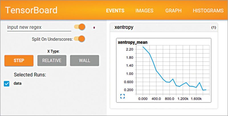
 In analogue electronics, oscillators and their implementation using integrated circuits (ICs) is an important subject. As 555 timer IC is easy to understand and flexible enough to suit diverse applications, it is used in astable multivibrator (oscillator) configuration for study purpose. While covering the topic in the classroom, instructors often use circuit simulators such as Proteus and TINA to show the output waveform variation of 555 timer IC by changing the resistor or capacitor values.


 ESP32 is a single chip 2.4 GHz Wi-Fi and Bluetooth combo chip designed with TSMC ultra low power 40 nm technology. It is designed and optimized for the best power performance, RF performance, robustness, versatility, features and reliability, for a wide variety of applications, and different power profiles.


