Quantcast
Channel: EFY Bureau – Electronics For You
Viewing all 5950 articles
Browse latest View live

Design smartly with Altium 2017

$
0
0

Altium is one of the most popular design software worldwide. With its large component libraries and smart features, it outshines all its rival software. Year after year, the software keeps updating. Here we focus on the latest version, Altium 2017.

What is new

Altium is an all-in-one comprehensive software with a seamless exchange of design data. Be it schematic capture to PCB layout, or viewing MCAD constraints to providing a natural electronics workflow, Altium does it all. It adopts a much more efficient approach with user-defined enhancement.

Object-specific keep-outs

Designers face a lot of problems in routing and spacing between components. For instance, if high-voltage paths are not taken care of during design, these can cause damage to the circuit. Designers need to ensure that these have enough creepage and clearance distance from other tracks and components.

To explain, let’s consider the case of an LED driver manufacturing firm, where a designer designed a PCB without keeping in mind voltage differences across each point. During high-voltage test, the circuit failed with a high noise and copper peeling off.

Altium 2017 helps to overcome this issue by pointing out high-voltage areas or prohibited zones known as keep-out areas during designing. Besides, it has upgraded PCB routing.

Active routing

Whether the layout is single-layered, double-layered or multilayered, routing is now easy with Altium 2017’s active routing feature. From a single track to multiple tracks, all can be managed with a single click. Just select the nets and map-out the intended routing area. The tool not only saves time but also increases the efficiency greatly. Designers can produce multilayer boards with high-class routing.

Object-specific keep-outs (Image courtesy: https://i.ytimg.com)

Fig. 1: Object-specific keep-outs (Image courtesy: https://i.ytimg.com)

Track glossing

The glossy feature lets designers clean up the routing segments and areas, giving the best finish to the end-product. It acts like an optimisation tool for quality and length of every net on the PCB, allowing automated alignment of routing paths.

Dynamic components/net selection

Designers can move, cut, paste or select any object in the layout easily. Earlier, during these functions, all the components used to get selected, whether required or not.

Active routing (Image courtesy: https://i.ytimg.com)

Fig. 2: Active routing (Image courtesy: https://i.ytimg.com)

Dynamic copper

This feature helps designers to maintain the copper volume around components, holes and vias as per the standard value of manufacturing. It easily combines copper shapes as per the layout requirement. Thus, judicial use of copper helps designers and manufacturers to save costs on copper usage.

Back drilling

Signal attenuation, crosstalks and reflections are the major drawbacks of any design layout. Even if the designer creates a design with perfection, disturbances caused due to vias, copper pads, tracks and component placement lead to improper results in PCBs designed for high-speed applications.

Backdrilling feature in Altium 2017 helps designers to automatically skip vias that may create issues during design in a particular segment of the PCB.

Back drilling (Image courtesy: https://i.ytimg.com)

Fig. 3: Back drilling (Image courtesy: https://i.ytimg.com)

Auto-cross probing

Designers can quickly navigate between the PCB layout and the schematic in a single window, which helps them to net-list the components, nets and pins of components as well.
Last but not the least

With its new powerful features, Altium 2017 aims to reduce the stress on designers while giving a cost-effective solution to manufacturers. It provides a unified environment for schematic, PCB and documentation. Besides, it provides a PCB development platform featuring MCAD DNA with a single database providing both electrical and mechanical data. Above all, 3D vision gives a realistic view of multi-model support, component placement, clearance checking and rigid-flex design.

Auto-cross probing (Image courtesy: www.altium.com)

Fig. 4: Auto-cross probing (Image courtesy: www.altium.com)

Sourcing of components from the supplier is possible in one go using the Altium Library or vault. There is also a design history, which details differences between the existing and previous versions of Altium.

Download latest version of the software


The post Design smartly with Altium 2017 appeared first on Electronics For You.


Increase Manufacturing Productivity Via Self-Aware Digital Factory

$
0
0

Silicon Valley has long been viewed as a cradle of innovation. Inventions that have come out of the Valley have impacted our lives and changed the way that we interact with each other and, really, the way that we live.

Drive around a 10-mile radius from Google’s campus in Mountain View, California, and you could stumble upon Apple while searching for the Googleplex. You can also send a shout-out by Yahooing across the wetlands at Facebook and be LinkedIn to both Cisco and Intel.

Who would have expected that the happy hour napkins from Walker’s Wagon Wheel would become the canvases to solve the problem du jour faced by the Fairchildren known as the “traitorous eight”? And that these napkins would turn into the patent drawings for new product ideas and the business plans that would spawn many other Silicon Valley companies? Look beneath all of this innovation, and you’ll find a simple single-gate silicon device from Mr. Schockley and Mr. Noyce, not to mention the wizardry of a Jobs and Woz.

Pondering the influence so far of Silicon Valley, we can reasonably assume that “the next big thing” is already being developed in some random building dotting a suburb along El Camino Real, affectionately known as The Royal Road. Of course, Silicon Valley isn’t alone in its penchant for innovation. Look around the world and you’ll find many of these communities. One unique factor about Silicon Valley is its high density of diverse technical talent, all concentrated in one area. Now, consider the creations we have already, and those that are taking root. It would be reasonable to assume that the one constant denominator to spark “the next big thing” will focus on further enhancing our quality of life. My feeling is that this is always a good gauge to determine whether a technology or new service will successfully influence or impact our daily lives.

Smart Sensors Leading to Informed Decisions

As our everyday products become smarter and connected, we’re quickly becoming a very data rich society. This trend highlights a few areas to watch. Smart sensors are playing key roles in helping us manage our lifestyles and improve the quality of goods and services in the manufacturing world. Securing and processing the voluminous amounts of data collected by these sensors is the key to the informed decision-making that can influence our actions or modify our behaviors. This, in turn, is bringing forth new levels of artificial intelligence (AI), which are giving machines more self-awareness. This probably brings to mind various parallels, such as Hal from the movie 2001: A Space Odyssey, or I Robot. Self-aware machines can determine their own limits and constraints, and make temporary adjustments to keep themselves working until they can be serviced, or work with other machines in their cells to compensate for their restricted performance. This level of machine intelligence will help enhance productivity and lead to a greater level of fail-safe performance to ensure that critical systems remain up and running.

Now, if we extract this performance need back to its silicon heritage, it becomes clear that a whole new class of products is needed to improve performance flexibility. This new class of silicon products will have the ability to self-adjust its parameters to provide a flexible I/O solution. In my view, creating silicon solutions that can make configuration choices on-the-fly is the next big thing! One example can be found in the company’s newest industrial IoT (IIoT) demonstration platform, the Pocket IO. The IO-Link standard is being adopted and integrated quickly into automotive and factory automation environments. As this happens, we’re seeing new levels of adaptive manufacturing, which in turn call for silicon solutions with self-configuration capabilities. With all of this innovation underway, it probably won’t be long before we start seeing self-aware digital factories—and benefiting from the productivity boost they can deliver.


The post Increase Manufacturing Productivity Via Self-Aware Digital Factory appeared first on Electronics For You.

New tool support for the new LPC54018 MCU-based IoT module

$
0
0

IAR Embedded Workbench supports the new NXP® Semiconductors LPC54018 MCU-based IoT module featuring onboard Wi-Fi and support for newly launched Amazon FreeRTOS from Amazon Web Services (AWS)

Uppsala, Sweden—December 20, 2017—IAR Systems®, the future-proof supplier of software tools and services for embedded development, announces tool support for the new LPC54018 MCU-based IoT module from NXP Semiconductors. Using the leading development toolchain IAR Embedded Workbench® for Arm® will enable developers to quickly and easily create powerful connected applications based on the new module.

The LPC54018 MCU-based IoT module includes support for Amazon FreeRTOS and provides a seamless Wi-Fi connection to Amazon Web Services (AWS), enabling developers to create secure, cost-effective IoT solutions. The module offers unlimited memory extensibility, a root of trust built on the embedded SRAM physical unclonable functions (PUF) and on-chip cryptographic accelerators. Thanks to the easy-to-use software libraries of Amazon FreeRTOS, cloud on-boarding and over-the-air device management is made easy. Now available for this IoT module are development tools from IAR Systems, which provide leading code optimization technology and extensive debugging functionality coupled with professional technical support offered globally.

Thanks to outstanding speed optimizations, IAR Embedded Workbench for Arm and the included IAR C/C++ Compiler™ generate very fast and efficient code. With the shortest possible execution times, it is the ultimate choice for development of high-performance, low-power applications such as new innovations built on this new IoT module. To enable extensive debugging and profiling, the toolchain includes features such as complex code and data breakpoints, runtime stack analysis, call stack visualization, code coverage analysis and integrated monitoring of power consumption. Through add-on tools for static analysis and runtime analysis, developers gain complete code control.

“We recently announced support for the new IoT microcontroller operating system Amazon FreeRTOS from Amazon Web Services,” says Anders Lundgren, Product Manager, IAR Systems. “This support in combination with the powerful code optimizations and debugging capabilities of IAR Embedded Workbench will enable developers to leverage the full potential of the new IoT module from NXP.”


The post New tool support for the new LPC54018 MCU-based IoT module appeared first on Electronics For You.

Security Predictions for 2018

$
0
0

INDIA – December 20, 2017 – The security threats and breaches of 2017 have set astounding new records for personal data invasion. From WannaCry to Petya, the list of sophisticated and far-reaching breaches grows almost daily. In 2017, breaches impacted hundreds of millions of people globally.

The security mission to protect, detect, and respond, has remained the same for everything from IT networks and data storage to payment systems and IoT devices. In the past ten years, a tremendous wave of technology innovation has been developed to help protect and detect. Yet, the most neglected area of security is the part that can be controlled – the response. With the increased trend of security issues, the top management of organizations is looking into the need for intelligence and resilience to security and finding ways to tackle it.

As per a recent report, India’s IT spending is expected to grow to $ 1.7 billion in 2018 from the current $1.5 billion in 2017 including IT outsourcing, implementation and consulting services. India has embarked on a journey of digital transformation with initiatives such as cashless economy and mandatory authentication linkage through a common biometric data platform. While it is impossible to stop innovation in a country where ‘Digital India’ is getting a push, there are concerns about incorporating security right at the beginning. With the deployment of IT security solutions, enterprises need to protect their data, manage the resources and networks.

Presenting his outlook for 2018; Edgar Dias, Managing Director, ServiceNow India said, “We live in a world where security is about giving the access of right content to the right user. There is a growing need for every organization to adopt serious measures to combat security threats and maintain a balance between protect and response measures more proactively rather than reactive. Improvement in technology will come only through increased awareness amongst businesses and organizations. ”

As 2017 draws to a close, ServiceNow looks at a few top security trends to watch in 2018:

Prediction 1: Security “Haves” and “Have-nots” emerge.

Security teams struggle to quickly determine whether incidents are worth a response. Many organizations use dozens of security tools that create and funnel massive volumes of signal onto the desk of the security professional. Analysts use spreadsheets and email to manage reacting to this signal, and the sheer volume of alerts results in analysts spending too much time researching incidents.

In 2018, we will see security Haves and Have-nots emerge between those that begin to automate this research portion of security response and those that don’t. Companies with the tools and culture to embrace automation, and put technology to work for real business enablement, will perform better than those that don’t.

The Haves will be expected to report on security operations as a key part of their day-to-day business. They will have scalable processes in place and will be in a position to measure progress. Automation will help them better determine which systems to patch and when. They will respond to phishing attacks in minutes rather than days. For the Haves, this will be a point of pride.

The beauty for the Haves is that their security people will be freed from mundane and time-consuming manual research. They will have more time to focus on strategic projects that fortify the organization. This new approach extends beyond security. Automation is so effective it becomes a rising tide that lifts all ships, operating in virtually all areas of business.

Prediction 2: Security gains a seat in the boardroom.

Security programs are about tradeoffs and minimizing risk. To achieve greater success, security teams need to better articulate those tradeoffs by putting the risk and material consequences into business terms, fundamentally bringing security into their business strategy. CISOs need to help executives and board members understand the ROI, cost-benefit analysis, and security program tradeoffs by articulating the business risk versus business value.

In the coming year, we will see CISOs do more to present their security concepts and programs in business terms. Talking about securing data is one thing, but demonstrating the value that security offers the business is something else. This will eventually apply to every aspect of the business, but most immediately applies to regulatory compliance, potential lost revenue, customer relationships, legal liability, competition, intellectual property, stockholder loyalty and brand protection.

The boardroom needs to take a step toward security, and security operations needs to take two steps toward the boardroom. Bridging the knowledge gap between security leadership and the board provides the framework to ensure effective security by helping all parties assess the risks and decide how to mitigate them.

Prediction 3: A breach enters our physical lives.

There is a difference between information and physical security. The breaches that plague organizations today are primarily information security violations. While painful, having credit card information, a social security number, or personal digital information stolen does not result in physical harm to the victim. In 2018, we will see a breach impact our physical, personal lives. It might be a medical device or wearable that is hacked and remotely controlled. Perhaps it will be an industrial IoT device or self-driving car that gets compromised. Or something closer to home – literally. Devices from the garage door to the refrigerator are becoming smarter and more connected. The impact of such an attack will force government, business and individuals to take a closer look at the security of our infrastructure.

The post Security Predictions for 2018 appeared first on Electronics For You.

Industrial Transportation: Powering After-Market Electronics and Infrastructure

$
0
0

Industrial transportation electronics is a broad category. It includes after-market additions for automation and entertainment in cars, trucks, trains, planes, and ships. It also includes infrastructure automation for roads, sea-lanes, trains, and air traffic control to move people and goods more efficiently.

Over the last few decades, after-market automotive products drove remarkable innovation, from infotainment and telematics to ADAS. Examples include GPS, audio, seat back video, rear-view cameras, parking sensors, charging ports, keyless entry, and others. Today, we see all these features integrated into the cars and trucks by OEMs. However, there is a continuous rollout of novel after-market technologies being developed by companies worldwide. Recent innovations include fleet management, on-board diagnostics, heads-up display, gesture-controlled navigation, network gateways, driver assistance, keyless/biometrics-based entry/exit/driving, and freight control/monitoring. These technologies have found places not only in cars and trucks but also in trains, ships, avionics, and defense applications.

Transport infrastructure automation to move people and goods more efficiently includes HOV lane control, parking/toll, fare meters, traffic control, and others. Numerous innovations have made faster movement, on-time schedules, and fewer accidents possible.
In this article, we will discuss the key market trends and customer needs which are presenting new challenges for power supply design for after-market technologies and transport infrastructure automation. Then, we’ll explore solutions to address these challenges, with a special emphasis on power architecture.

Market Trends

One of the most dynamic applications in industrial transportation today is fleet management and logistics. With goods being manufactured and shipped from various regions, states, countries or even overseas, tracking the goods is a big business. For example, when perishables are transported, it is important to ensure they are consistently kept under regulated temperature, pressure, or other parameters. Similarly, secure goods require sensors to track location and entry access. Driver safety is also essential, requiring data from cameras monitoring driver alertness and GPS systems tracking vehicle location.

This data is logged using wireless networks and cloud infrastructure, and complex algorithms synthesize the data to make real-time decisions on route and/or driver safety. Several GPS navigation companies have entered the fleet management market, providing hardware and software products and services. North America, Europe, Japan, and Korea each have a long history of advanced fleet management systems. More recently, Latin America, China, and India are adding this capability, presenting a huge growth opportunity. Interestingly, Israel has several players that develop products for consumption in Israel, Africa, Europe, and the rest of the world.

Some might think there is not much innovative technology to add to infotainment, what with so many audio/video, smartphone, and navigation options coming as standard features from OEMs. Yet, trends in this area include integration beyond a simple smartphone interface to add heads-up display (HUD) that projects the phone screen onto the windshield glass with gesture control to navigate between maps and video calls, or other salient features like weather, stock ticker, calendar, etc. Seat back screens to mirror the phone screen for rear passengers is also an active product development area.

Advanced driver assistance systems (ADAS) is a growing market today. After-market ADAS includes parking sensors, rear-/extended-view cameras, lighting, traffic warnings, car-to-car (vehicle-to-vehicle) interface, and others. Several manufacturers are working on solutions that enable drivers to avoid unintended lane departures, collisions, pedestrians, and road hazards, as well as drive within the speed limit.

With the amount of time people spend in cars in highly congested urban cities, many cars and buses are also adding wireless gateways. This enables passengers to continue to work during long commutes between home and office/school.

Typical System Architecture

Here is a typical fleet tracking/management system architecture:

Figure 1: Typical fleet tracking/management system architecture

Power Architecture

The fleet tracking/management device is powered by the vehicle battery, typically 12V in cars and 24V in many trucks. As an after-market add-on, it faces a much harsher power management environment than a well-bounded OEM device. Most devices also have a rechargeable backup battery, typically 3.6V, intended to last two or three days when the main battery power is lost. From the main battery source, the front-end electronics are protected against transient and fault conditions. The protected voltage is converted to useable, lower voltages (3.3V, 2.5V, 1.2V, etc.) by step-down DC-DC converters and LDOs to power various digital logic and analog ICs.

Figure 2: Typical fleet tracking/management power architecture

Protecting the Device from Faults

Like many other electronics that draw power from a vehicle battery, the fleet tracking/management device must be protected from voltage surges commonly known such as load dump, regenerative braking, long cable ringing, etc. Load dump is an event where the battery cable is suddenly disconnected while the alternator is spinning, putting high energy back to the vehicle power cable where there is nothing to absorb it, causing high voltages that could destroy unprotected electronics. Regenerative braking occurs in an electric vehicle when the driver applies the brake; the vehicle kinetic energy is captured by the motor and sent back to charge the battery. Due to the high energy, high di/dt nature of regenerative braking, there will be high voltage ringing associated with this event.

The post Industrial Transportation: Powering After-Market Electronics and Infrastructure appeared first on Electronics For You.

Micro-Solder Pot

$
0
0

To make a great solder joint, component preparation is a must. It is very important to clean component leads, wires and contact surfaces prior to soldering with isopropyl alcohol. Remember, tinning component leads and wires makes the actual soldering of joints quick and efficient. Tinning involves putting a thin layer of solder on the component/wire tips, which assists greatly in transfer of heat to solder joints.

Obviously you need to strip the enamel off the copper wire (ECW/magnet wire) to prepare it for soldering. However, tinning a small-gauge wire (>18SWG) using an ordinary soldering iron is quite cumbersome.

You can use this home-made micro-solder pot not only to strip the heat-strippable enamel but also to put a thin layer of solder on the stripped part. Note that wire leads that are insulated with non-heat-strippable enamel should be scraped clean before the micro-tinning process.

This do-it-yourself project is a true recycling project as it turns the popular soldering iron element into a micro-solder pot for your electronics lab. At the heart of this project is a 25W soldering iron element from Soldron (Fig. 1). Another main component required is a standard 5mm hot-air nozzle for the quick hot-air SMD rework station as shown in Fig. 2. Apart from these, you only need a handful of inexpensive components and accessories as mentioned in the parts list!

Soldering element with nozzle

Fig. 1: Soldering element with nozzle

Construction

First, plug the hot-air nozzle directly into the tip of the soldering iron element. Then secure the nozzle over the tip using a high-temperature sealant/adhesive. The nozzle forms the solder pot. When the soldering element is heated up, the nozzle too becomes hot. Fig. 1 shows an example of micro-solder pot constructed in this way.

Nozzle and other accessories

Fig. 2: Nozzle and other accessories

Fig. 3 shows a very simple power supply circuit, which can be easily constructed on a small piece of perforated prototyping board. The 230V AC power line voltage is fed to the soldering iron element through the on/off switch. The 1N4007 diode converts the 230V AC mains into a safe power supply voltage for the soldering iron element. The red LED indicates the power on/off status.

Circuit of the micro-solder pot power supply

Fig. 3: Circuit of the micro-solder pot power supply

Tinning procedure

Fill your micro-solder pot with adequate amount of solder wire, switch it ‘on’ and let it heat up to the right temperature. As the temperature of the pot rises, you can see the solder wire in the pot melting away. After a few minutes, you can see molten solder in the pot. Next, determine the length of the wire/component lead which must be stripped. Insert the lead end of the wire into the solder pot and wait for a few seconds. Finally, slowly pull the lead back out of the solder pot. No doubt, what you get is a nicely tinned wire/component lead! Fig. 4 shows tinning on a stripped wire end.

Fig. 4: Tinning before and after

Caution. This micro-solder pot is meant for experienced electronics hobbyists.

components required

Inexperienced persons unfamiliar with heat soldering tools and molten solder characteristics should not use it. To this effect, provide a warning notice on the use of the hot pot.


The post Micro-Solder Pot appeared first on Electronics For You.

Modeling and Simulation

$
0
0

Digital Modeling is a process of creating a computer generated model of an object that exactly replicates the form of an actual object. However, it is not all about 3D designing. Design modeling covers designing & simulating the product before printing hardware. Here we talk about the various steps involved in modeling & simulation. In the presentation given below, you will be getting a complete overview of the following points:

  • Introduction to modeling and simulation
  • Types
  • Applications
  • Various steps involved in the process(es)
  • Choosing an simulation tool
  • Case studies

Simulation Powerpoint- Lecture Notes from Kesavartinii Bala Krisnain


Feel interested? Check out other electronics basics in the learning corner.

The post Modeling and Simulation appeared first on Electronics For You.

Automatic Railway Gate for Unmanned Railway Crossing

$
0
0

The aim of this project is to save lives of people who are crossing unmanned railway crossings; by providing an automatic railway gate solution. There are many accidents occurred and lives are lost while crossing the unmanned railway crossings in India.

Materials Used:

  • Wood
  • Thermocol
  • Train and Track,

Electronic components:

  • IC L293D
  • IR Sensor set
  • Arduino Uno
  • DC Motor
  • GSM Module
  • Solar Panel (Next phase of project)
  • Bread Board, wires and Power supply

Circuit operation

Arduino gives a pulse to the ultrasonic sensor. The ultrasonic sensor has a transmit eye and a receive eye. When the Arduino gives a pulse to ultrasonic sensor, the transmit eye transmits an ultrasonic wave. When the train arrives, the ultrasonic wave bounces back. Then the receive eye receives the ultrasonic wave. It gives signal to the arduino; which calculates the distance.

The formula to calculate the distance is to multiply the speed of sound with the time taken for the ultrasonic wave to bounce back and dividing the answer by two.

Then the L293D and the buzzer gets signal from the Arduino and it gives output to the motor. And then Railway gate falls/closes. After the train crosses, the gate goes up/opens. The Motor for Railway gate can also be powered from Solar Panel.

Applications & Benefits

If installed in unmanned railway crossings, it prevents accidents and saves lives.

  • Saving lives of people
  • Eco friendly solution.
  • Low cost
  • Can be easily installed

Program

//pin which triggers ultrasonic sound
const int pingPin = 13;

//pin which delivers time to receive echo using pulseIn()
int inPin = 12;

//range in cm which is considered safe to enter, anything
//coming within less than 5 cm triggers red LED
int safeZone = 5;

//LED pin numbers
int right = 5;
int left = 2;
int buzzer =10;

void setup() {
// initialize serial communication
Serial.begin(9600);
}

void loop()
{
//raw duration in milliseconds, cm is the
//converted amount into a distance
Int duration, cm;

//initializing the pin states
pinMode(pingPin, OUTPUT);
pinMode(right, OUTPUT);
pinMode(left, OUTPUT)
pinMode(buzzer, OUTPUT);h
// SETTING TO LOW
digitalWrite(left, LOW);
digitalWrite(right, LOW);

//sending the signal, starting with LOW for a clean signal
digitalWrite(pingPin, LOW);
delayMicroseconds(2);
digitalWrite(pingPin, HIGH);
delayMicroseconds(5);
digitalWrite(pingPin, LOW);

//setting up the input pin, and receiving the duration in
//microseconds for the sound to bounce off the object infront
pinMode(inPin, INPUT);
duration = pulseIn(inPin, HIGH);

// convert the time into a distance
cm = microsecondsToCentimeters(duration);

//printing the current readings to ther serial display
Serial.print(cm);
Serial.print(“cm”);
Serial.println();

//checking if anything is within the safe
digitalWrite(buzzer, HIGH);
digitalWrite(left, HIGH);
delay(3000);
digitalWrite(left, LOW);
delay(3000);
digitalWrite(right, HIGH);
delay(3000);
digitalWrite(right, LOW);
digitalWrite(buzzer, LOW);
}

}//void loop ends

int microsecondsToCentimeters(int microseconds)
{
// The speed of sound is 340 m/s or 29 microseconds per centimeter.
// The ping travels out and back, so to find the distance of the
// object we take half of the distance travelled.
return microseconds / 29 / 2;
}


The post Automatic Railway Gate for Unmanned Railway Crossing appeared first on Electronics For You.


1 MHz Bandwidth Current Sensor ICs with 3600 VRMS Isolation

$
0
0

Worcester, MA – December 21, 2017– Allegro MicroSystems, LLC adds a new generation of high bandwidth current sensor ICs to their existing family of devices. The Allegro’s ACS732 and ACS733 current sensor ICs provide a compact, fast, and accurate solution for measuring high-frequency currents in DC/DC converters and other switching power applications. These devices are the first 1 Mhz offerings from Allegro to offer 3600 VRMS galvanic isolation ratings. The current sensor ICs are Hall-effect-based and include user-configurable overcurrent fault detection. These features make them ideally suited for high-frequency transformer and current transformer replacement in applications running at high voltages.

The ACS732 and ACS733 are suitable for all markets, including automotive, industrial, commercial, and communications systems. They may be used in motor control, load detection and management, switch-mode power supplies, and overcurrent fault protection applications. The devices are fully calibrated at the Allegro factory to provide a high accuracy solution over the entire operating temperature range.

The fully integrated wide body SOIC-16 package has a typical resistance of 1 mΩ, providing low power loss and reduced bill of materials that allows for easy implementation. Applied current flowing through the copper conduction path generates a magnetic field that is sensed by the IC and converted to a proportional voltage. Current is sensed differentially in order to reject external common-mode fields. The current-carrying pins (pins 1 through 8) are electrically isolated from the sensor leads (pins 9 through 16). This allows the devices to be used in high-side current sensing applications without the use of high-side differential amplifiers, isolators, or other costly isolation techniques.

The ACS732 and ACS733 are provided in a small, low profile, surface-mount SOIC-16 wide-body package. This package is lead (Pb) free, with 100% matte-tin leadframe plating (suffix –T). The ACS732 and ACS733 are priced at $1.96 in quantities of 1,000.


The post 1 MHz Bandwidth Current Sensor ICs with 3600 VRMS Isolation appeared first on Electronics For You.

Advancing Solutions Underpin Rapid Progression of Fast Moving Technology Sectors

$
0
0

Consumer Electronics Show (CES) – Venetian 3302 – LAS VEGAS, NV. – December 19, 2017 – ON Semiconductor, driving energy efficient innovations, will be focusing on its technologies that are enabling the progression towards fully autonomous driving and increased electronic content in connected vehicles at the 2018 Consumer Electronics Show (CES) in Las Vegas. Among multiple exhibits will be interactive demonstrations that will allow visitors to experience and understand the company’s industry leading solutions in these exciting and fast moving areas of technology.

The Automotive Image Sensing Applications Platform demonstration will enable attendees to see the real-world performance of the company’s latest image sensors in various Advanced Driver Assistance Systems (ADAS) applications including front view, surround view, rear view and driver monitoring. Image sensors from ON Semiconductor achieve current and future industry performance level requirements in terms of resolution, clarity, mixed and poor light conditions and robustness for level three driving autonomy and beyond.

As the extent and diversity of vehicle electronic content continues its rapid upward trend in areas such as safety, infotainment, comfort and convenience, ON Semiconductor’s broad range of technologies and system solutions continue to be fundamental to their development and implementation. At CES, the company’s Intelligent Automotive Solutions demonstration vehicle will showcase the advanced connectivity features of ON Semiconductor automotive products that bring multiple benefits including wire replacement with associated weight, space and complexity savings, increased safety and a better overall driver experience.

The demonstration will include technologies in the fields of wireless actuation and communications, battery-free sensing, electronic fuses, USB Type-C and power delivery and Bluetooth low energy technology for several in-car applications using a new variant of the hugely successful RSL10 radio System-on-Chip (SoC)designed and qualified specifically for automotive.

A highly interactive Automotive Virtual Reality demonstration will allow visitors to look under the hood and sit inside a 3D model of a next generation vehicle. Outfitted with cutting edge automotive solutions, this demo will allow users to experience ON Semiconductor solutions for semi-autonomous/autonomous driving scenarios including collision avoidance, drowsy driving, and level 5 fully autonomous driving.

In addition to automotive applications, ON Semiconductor will illustrate its expertise and innovations in areas such as smart passive sensing, image sensing, USB Type-C and integrated power management solutions that are enabling the development of compelling new end products across multiple sectors. Many of these can be seen on display around CES, including IoT applications relating to smart home / smart buildings, security and surveillance, and augmented and virtual reality (AR/VR) for both consumer and industrial applications.


The post Advancing Solutions Underpin Rapid Progression of Fast Moving Technology Sectors appeared first on Electronics For You.

Efficient Egg Candler

$
0
0

Candling eggs while they are incubating is the proven method to test them for fertility. Often, egg candling is done using a light source to channel enough light into the egg in order to determine whether the egg is developing into a chick (see Fig. 1). The light source is usually an incandescent lamp or an LED. Many users prefer an LED as it does not create enough heat to harm the egg.

Typical way of observing the egg through a light source (Courtesy: www.incubatorwarehouse.com)

Fig. 1: Typical way of observing the egg through a light source (Courtesy: www.incubatorwarehouse.com)

Here we describe a battery-powered LED egg candler to detect embryonic development or separate eggs with cracked shells. Being battery-powered, the egg candler can be taken anywhere. Also, it is more convenient to use: Just put the egg on the egg base and observe for embryonic growth.

The author’s prototype is shown in Fig. 2.

Author’s prototype with battery

Fig. 2: Author’s prototype with battery

Circuit and working

The circuit (shown in Fig. 3) has a 4V lead-acid SMF battery (BATT.1) and a 1-watt star white LED (LED2) on the right side. On the left side is a transformerless power supply to charge the battery. That is, the battery charger is powered by 230V AC mains supply through a transformerless circuit. A 5V Zener diode (ZD1) is used as a pre-regulator to protect low-voltage circuit components from damage by the high-voltage input.

Circuit diagram of the egg candler

Fig. 3: Circuit diagram of the egg candler

LED1 is the ‘charger on’ indicator. A 1-kilo-ohm resistor (R2) limits the working current of LED1, while a 2.2-ohm resistor (R4) controls the current flowing through LED2. A 4.7-ohm resistor (R1) is used as the inrush current limiter, and a 390-kilo-ohm resistor (R3) across 1µF capacitor (C1) works as the bleeder resistor.

The transformerless power supply offers advantages of low cost and light weight. Also, it is reliable when operating with nominal load.

Construction and testing

An actual-size PCB layout of the egg candler is shown in Fig. 4 and its components layout in Fig. 5. Link the battery to the star white LED (LED2) to generate the requisite light output. LED2 lights up when on/off switch (S1) is closed.

Actual-size PCB layout of the egg candler

Fig. 4: Actual-size PCB layout of the egg candlerComponents layout for the PCB

Fig. 5: Components layout for the PCB

Download PCB and component layout PDFs: click here

The egg base is made using a small bottle cap (23-25mm diameter) modified to suit the needs. A hole is made at the bottom of the cap for the wires of star white LED to pass through (Fig. 6). Besides, a small screw is fitted through another hole with washer and nut for the purpose of mounting later. Glue LED2 to the cap.

Mechanical egg base design using a bottle cap

Fig. 6: Mechanical egg base design using a bottle cap

The finished egg base can be affixed to the top of a wooden/acrylic box with the circuit board (and battery) attached to the inner bottom of the enclosure. Refer Fig. 7 for mechanical design outline starting from the bottle cap to the proposed finished enclosure. The egg base prepared by the author is shown in Fig. 8.

Mechanical design outline

Fig. 7: Mechanical design outline

Fig. 8: Author’s egg base for the egg candler

After successful construction and initial testing, your home-made egg candler is ready for periodic candling of eggs.

Caution. Beware, any experiment involving 230V AC mains voltage demands extreme care and absolute respect for electrical safety guidelines!


The post Efficient Egg Candler appeared first on Electronics For You.

The Impact of Innovation on our Lives in 2018

$
0
0

One of the benefits of my role as President and CEO of Analog Devices, is traveling the world to meet with customers from a variety of industries and regions and hearing their perspective on the technological, business, and market challenges they face. Our customers produce the wide variety of electronic equipment that we all rely on for transportation, healthcare, communication, and many of the benefits of modern life. Our discussions typically focus on both their current needs to intelligently bridge the physical and digital worlds as well as on the innovation they want to enable in the future. I have drawn upon those conversations and other research to compile the following five technology macro-trends that I believe will have the greatest impact on business and society during 2018.

Artificial intelligence

Customers in every market segment are feverishly trying to understand the value of artificial intelligence and machine learning for their businesses, mirroring efforts of a decade ago to realize the benefits of digitalization. The focus on utilizing AI will accelerate in 2018, with the performance/affordability barrier continuing to be broken down and targeted applications of AI achieving financial and application-level impact in Industrial settings. For example, AI has progressed to a point where, industrial robots are able to learn and adapt to new environments or unfamiliar objects without being specifically trained.

AI at the edge will begin transitioning from a novelty to a norm through innovation related to low-power processing, while intelligent edge computing will become a reality with context-enriched data and information driving smarter system partitioning between the edge and the Cloud.

Meanwhile the development of AI applications that rival human intelligence will remain squarely in the university research domain.

Autonomous/intelligent machines

Autonomous systems for cars, drones, and robots will continue to advance during 2018, but only to a certain point due to unresolved regulatory and technical issues. Nevertheless, over the coming months, we will continue to see progress in the adoption of autonomous systems through initiatives such as trial deployments of robo-taxis in limited areas. In particular, long-haul transportation such as trucking, and trains will be among the applications that experience true advancement of autonomous functionality in the near term.

Driven by the continuing quest for productivity gains, the drive to add intelligence to machines will also accelerate factory automation/Industry 4.0 initiatives. For example, advances in machine learning will significantly improve the ability of systems to provide valuable performance recommendations and predictions based on their own independent condition monitoring.

Ubiquitous wireless sensing networks and data

The combination of advanced materials, enhanced functionality, and MEMS is enabling breakthroughs in sensor form factors and cost, which will enable ubiquitous wireless sensor networks. Deployment of wireless mesh networking in IoT and Industrial applications will enable sensing capability to be added to existing systems without extensive rewiring.

However, end-to-end security from the sensor to the Cloud will be the gating requirement for Industrial customers to begin deploying Industrial IoT initiatives at scale.

The drive to make products and systems more intelligent will also increase the need to manage and analyze an ever-increasing flow of data. Data centers will require higher processing performance as the data load continues to increase, as well as advanced power management innovation to mitigate risk presented by high thermal levels in data center systems. We will also begin to see greater intelligence integrated at the edge node to begin to triage and tame the flow of data.

Machine-human interface

Mixed reality systems will continue to emerge and grow in popularity, with augmented reality and virtual reality ecosystems flourishing and stimulating innovation. As the use of commercial AR/VR systems accelerates, costs will decrease, and applicability will extend into spaces such as Industrial for off-site diagnostics and repair.

In addition, voice-as-user interface has now become an expectation, but this technology continues to face limitations, especially in noisy environments. Gartner predicts that in 2018, 30% of our interactions with technology will be through “conversations” with smart machines, meaning that technology and service providers need to invest now to improve currently limited voice interfaces.

Heterogeneous manufacturing

With the costs of deep-submicron development skyrocketing and Moore’s Law facing increasing technology and economic headwinds, heterogeneous integration of multiple technologies in a package, on a laminate, or even on a single silicon substrate will increase. New business models will emerge to capitalize on heterogeneous manufacturing, enabling recombinant innovation for small-scale semiconductor industry players who cannot afford to invest in state-of-the art IC lithographies. For suppliers with greater scope and scale, the addition of signal processing algorithms to silicon will increase the value of their solutions.

Conclusion

How will these trends evolve over the coming year? It is often said that the best way to predict the future is to create it. As semiconductor innovation will be the foundation for many of these emerging applications and analog technology will become even more critical in a data-hungry world, you can be sure that we at Analog Devices will be working diligently to make these predictions a reality in 2018.


The post The Impact of Innovation on our Lives in 2018 appeared first on Electronics For You.

Simple 8-bit Computer for Learning

$
0
0

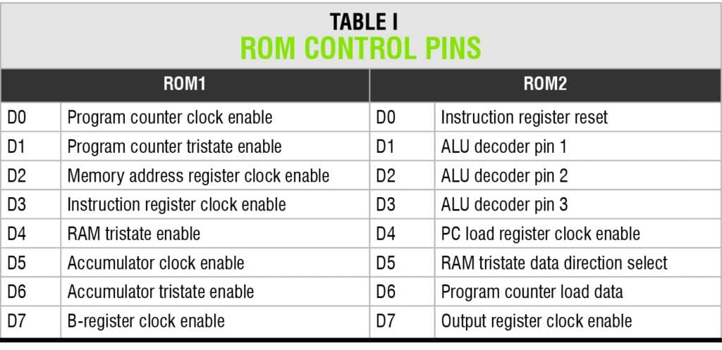
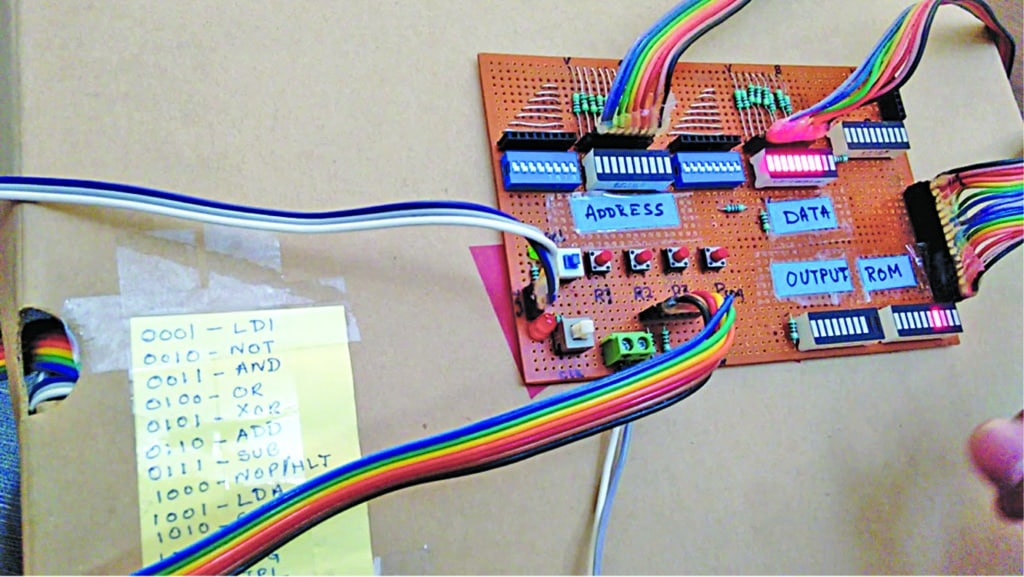
Computers take an input, process it as per a set of instructions and provide the output. These are general-purpose devices that can be programmed to carry out a set of arithmetic or logical operations automatically.

Intel 8008 was the first 8-bit microprocessor for the microcomputer system. The architecture of a microprocessor seems complex, but a computer can be entirely built with TTL logic chips without using any microprocessor/controller. This project helps you build your own computer while also providing an insight into the working of a general-purpose microprocessor as well as its construction mechanism.

Architecture

This 8-bit digital TTL computer is designed as per the architecture shown in Fig. 1. The entire processor circuit is powered from an SMPS as it consumes a lot of power. Voltage supply is 5V.

Processor architecture

Fig. 1: Processor architecture

The architecture has a common 8-bit bidirectional data/address bus. The arithmetic logic unit (ALU) consists of adder/subtractor circuit along with AND, OR, NOT and XOR gates to perform logical and arithmetical operations. The values for operation are stored in A-register (Accumulator) and B-register. The number of states and sequence of states for all the instructions are stored in the ROM. Two ROMs are used to control the sequence of operation for various modules in the system. ROMs provide 16 control lines for operation.
The output and enabling of different modules are controlled by EN pins of ICs or tristate buffers. For example, the ALU output is controlled by using tristate buffer at the end of each logic output. The ALU output selection based on the instruction is done by a decoder connected to ROM2 as shown in the circuit diagram Fig. 2.

Circuit of simple 8-bit computer

Fig. 2: Circuit of simple 8-bit computer

Typically, the sequence of operation is as follows:
1. The program counter (PC) is incremented
2. The PC value is loaded in the memory address register
3. The instruction is stored in the instruction register of the RAM at the address specified by the memory address register
4. The PC is incremented
5. The memory address register is updated with a new PC value
6. The LDI instruction loads the data in the accumulator specified by the memory address of the RAM
7. The instruction register is cleared for next instruction loading

The author’s prototype with five LED bar displays is shown in Fig. 3. LED bar displays show the status of output, data, address, instruction set and state. This helps in tracking how each instruction is being executed.

Fig. 3: Author’s prototype

Circuit and working

As can be seen from Fig. 2, inputs to the accumulator, B-register, output register, PC register and memory address register are fed through the 8-bit parallel address/data bus. The input to the ALU is provided by the accumulator and B-register.

The ALU outputs to the bus via tristate buffers. The accumulator also outputs to the bus via tristate buffer 74LS245N. The tristate buffers are controlled by enable (G) pin.

The PC register output is fed to the program counter, providing the value to be loaded in the counter. The PC outputs to the bus via a tristate buffer. The memory address register outputs to the multiplexer.

The multiplexer output is fed to address pins of the RAM (CY6264). Input/output pins of the RAM are connected to the bus via the tristate buffer (IC23). The DIR and G pins of the tristate buffer are controlled based on the instruction and data flow. The 4-bit LSB of the bus is fed to the instruction register (74LS173N).

The inputs to the counter (CD4029N) are grounded. The outputs of the instruction register and the counter are connected to the address pins of ROMs (AT28C64). The ROM outputs are connected to enable pins of various ICs to control the data flow based on the state and instruction.

The functions of different modules in the architecture are as follows:

Program counter.

The program counter provides the computer with the current address of the instruction to be executed.

Memory address register.

The memory address register (MAR) stores the current address for the byte to be read or written from the memory.

Multiplexer.

The multiplexer allows selection of address either from the MAR (in run mode) or the manual input (programming mode).

Instruction register.

The instruction register of a computer stores the current instruction that is being executed.

During the computer’s operation, the value stored in instruction register is the instruction opcode. It forms the four bits of middle-value address (A4-A7) for ROMs. The counter for the next state provides the four bits of LSB (A0-A3) for ROMs. The 3-bit output from the comparator (74LS85N) forms the MSB (A8-A10). Thus, the address (A0-A10) is fed to the two ROMs to generate the control logic for different modules.

The post Simple 8-bit Computer for Learning appeared first on Electronics For You.

Intuition Pro: The World’s First Intuition Enhancing Device

$
0
0

SYDNEY, Dec. 22, 2017 – A recent study by the University of Cambridge demonstrated that financial traders were “better at reading their ‘gut feelings’ than the general population – and the better they are at this ability, the more successful they are as traders.”

A possible explanation might be linked to the human subconscious itself and its ability to “access” future events. Recent studies have demonstrated that the human subconscious is gifted with predictive capability, which scientist have coined PAA – or Predictive Anticipatory Activity. PAA is the ability of the human subconscious to peak into the future a few seconds ahead of time. Although PAA has been observed with consistency over and over, scientists are still at work to find an explanation for this phenomenon. Some have argued that PAA is linked to Einstein’s Field Theory, where past, present and future are all interrelated. Recent research, such as Cambridge University’s research on traders, has found that people who are more in tune with their subconscious seem to be better at guessing the future – even if that future is a seemingly unpredictable future event, such as random event in a gambling environment.

The ability to consciously sense your subconscious bodily reaction is called interoception. Yet most of us, due to our rational upbringing, no longer pay attention to the interoception happening to our own body. In other words, we no longer listen or trust our gut feeling.

This is why Intuition Pro was developed. Intuition Pro helps you to regain your capacity to consciously sense signals from your subconscious. Training your interoception sense with Intuition Pro enhances the ability to sense minute subconscious bodily reaction, and since the subconscious can access the future… so can you!

The Intuition Pro App provides quizzes, and while the users undertake the quiz, the Intuition Pro device monitors the user’s subconscious body reactions. Subconscious levels are recorded for both right and wrong answers during both the guessing period and when the results are displayed. Subconscious levels during and after the guessing period are generally identical, this is a confirmation that the human subconscious anticipates the answer ahead of time. The guessing period corresponds to the intuitive zone. Since all the training quizzes are randomly generated, the results are one more confirmation that the subconscious can peak into the future and predict events that would normally be unpredictable. An algorithm generates an intuition score by analyzing the difference between the subconscious levels in the intuitive zone. The higher one’s ability to sense subconscious bodily reaction levels, the higher the intuition score. Gradually, users enhance their ability to sense their subconscious level and their predictive skills.

Intuition Pro devices benefit those making rapid decisions in a fast-paced, volatile market environment and also when events are randomly generated – such as a gaming environment. Founded in early 2017, Intuition Pro offers unique and revolutionary products to enhance your intuition and improve your decision-making skills. Missioned to pioneer neuroscience-based products for the betterment of people’s lives.


The post Intuition Pro: The World’s First Intuition Enhancing Device appeared first on Electronics For You.

Towards Soft Electronics for Shape-Shifting Circuits

$
0
0

Science fiction is inching closer to reality with the development of revolutionary self-propelling liquid metals—a critical step towards future elastic electronics. At present, electronic devices like smart phones and computers are mainly based on circuits that use solidstate components, with fixed metallic tracks and semiconducting devices. This leads to rigid structures. Besides, none of the current technologies is able to create homogeneous surfaces of atomically thin semiconductors on large surface areas that are useful for industrial-scale chip fabrication.

Advancements in electronics can be made through flexible and dynamically reconfigurable soft circuit systems. This involves taking electronics beyond the confines of solidstate circuits to soft-state circuits. The goal is to create elastic electronic components. These are a type of soft circuit systems that would function in a way analogous to biological cells. That means electronic circuits that can move independently and also interact with each other to construct new circuits. To achieve this, liquid metals are required.

The use of liquid metals in electronics has always fascinated the scientists due to their inherent advantages of fluidity and shape-shifting qualities. However, there are issues to be dealt with, like availability of only a few pure liquid metals at room temperature. Among liquid metals, non-toxic alloys of gallium so far seem to be the most promising candidate for realising the dream of truly elastic electronic components.

Gallium alloys: Liquid metals fit for electronics

Though all the pure metals listed in the table (next page) are liquid at room temperature, these are not suitable for use in electronics due to reactivity and stability problems associated with them. Liquid metals also consist of alloys with very low melting points, which form an eutectic that is liquid at room temperature. The standard metal of choice used to be mercury, but gallium-based alloys, which are lower both in their vapour pressure at room temperature and toxicity, are being used as a replacement in various applications.

Static circuit boards may one day give way to dynamic, changeable ones that can pop up on demand (Image courtesy: https://cosmosmagazine.com)

Static circuit boards may one day give way to dynamic, changeable ones that can pop up on demand (Image courtesy: https://cosmosmagazine.com)

Gallium shares similarities with aluminium, indium and thallium. It is commonly used to make alloys with low melting points, which are predominantly used in electronics. For example, gallium arsenide is used in microwave circuits. Some of the common gallium alloys are Ga-In-Sn, Ga-Al, Ga-In, Ga-Sb, Ga-Sn, Ga-Pb, Ga-Mg, Ga-Bi and Ga-Bi-Sn.

Gallium alloys are ideal candidates for flexible electronics as these liquid metals are malleable and conductive. Also, the researchers could manipulate gallium alloys easily without touching them. For liquid metal based flexible printed electronics, the ideal properties of the core manufacturing material, i.e., room-temperature liquid metal—currently mainly represented by gallium and its alloys—are excellent resistivity, enormous bendability, low adhesion and large surface tension. With such properties, any droplet of liquid metal contains a highly-conductive metallic core and an atomically thin, semiconducting oxide skin. These are the key parameters for developing flexible electronic circuits.

The suitability of gallium for future electronics was demonstrated recently by researchers in a study in which they (researchers) immersed liquid metal droplets in water. Due to ionic interactions, the metal was able to move freely in three dimensions—the key to developing a suitable material in understanding the influence of the surrounding fluid on the metal. The researchers showed how adjustments made to concentrations of acid, base and salt components in the water were influential. Getting this right should open the door to creating moving objects, switches and pumps—each necessary for flexible electronic devices.

Technological developments

Scientists are concerned that the fundamental technology of electronics has not progressed much for many decades, and mobile phones and computers today are no more powerful than they were five years ago. They are searching for a technology that will allow them to increase the processing power of electronic components.

Researchers believe that the answer lies in ultra-thin components made by printing with liquid metals. The 2D printing technique can create many layers of incredibly thin electronic chips on the same surface, dramatically increasing the processing power while reducing costs. Using liquid metals to create integrated circuits that are just atoms thick could lead to the next big advance in electronics. The process opens the way for production of large wafers around 1.5 nanometres (nm) in depth; a sheet of paper, by comparison, is 100,000nm thick. Other techniques have proven unreliable in terms of quality, scaling and functioning at very high temperatures (550 degrees or higher). Researchers hope that creating electronic wafers just atoms thick could overcome the limitations of current chip production. It could also help produce materials that are extremely bendable, paving the way for flexible electronics.

Metals like gallium and indium have a low melting point. These produce an atomically thin layer of oxide on their surface that naturally protects them. It is this thin oxide which is used in fabrication method. By rolling the liquid metal, the oxide layer can be transferred onto an electronic wafer, which is then sulphurised. The surface of the wafer can be pre-treated to form individual transistors. This novel method has been used to create transistors and photo-detectors of very high gain and very high fabrication reliability in large scale.

The post Towards Soft Electronics for Shape-Shifting Circuits appeared first on Electronics For You.


Controlling Appliances through Google Assistant using ESP8266 and IFTTT

$
0
0

In this tutorial video, the presenter will shown how you can contorl your home appliances with just your voice by the help of google assistant from anywhere in the world.

  • Watching this video you’ll get to know about the following:
  • Adadfuit MQTT broker(Making account and feeds)
  • What is IFTTT, how does it work and how to make applets in IFTTT.
  • Creating wifi controlled Relay using esp8266

Important link: Adafruit MQTT Library

Courtesy: techiesms


The post Controlling Appliances through Google Assistant using ESP8266 and IFTTT appeared first on Electronics For You.

The Next Wave of Job Opportunities, Brought to You by the IoT (Part 1 of 4)

$
0
0

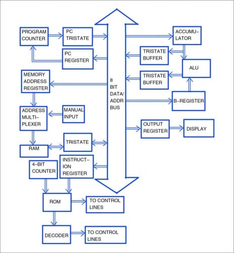
This article is the first of a four-part series that will look at the IoT’s impact on the following:

  • Labor and jobs
  • Privacy and security
  • Energy efficiency
  • Sports and health

The numbers are impressive for the Internet of Things (IoT):

IHS forecasts that the IoT market will grow from an installed base of 15.4 billion devices in 2015 to 30.7 billion devices in 2020 and 75.4 billion in 2025 — an increase of 60 billion devices over 10 years. (Source: IoT platforms: enabling the Internet of Things, March 2016)

Bain predicts that by 2020, annual revenues could exceed $470 billion for IoT vendors selling hardware, software and comprehensive solutions. (Source: Bain & Company, How Providers Can Succeed in the Internet of Things, August 2016)

As the IoT pushes automation to new heights, people will perform fewer and fewer “simple tasks.” Does that mean the demand for highly technical employees will increase as the need for less-technical employees decreases? What will be the immediate and long-term effects on the overall job market? Let’s take a look how the IoT will impact jobs and the labor market.

The obvious: Immediate, in-demand jobs and skills include high tech and data analytics

Millions of devices will come online over the next few years, and a considerable number of applications will emerge. It’s no surprise that tech companies — as well as large global companies across many industries — are busy creating IoT strategies to capitalize on this trend.

Yet many of these companies don’t have the know-how or in-house talent to realize their new IoT strategies. This is good news for the job market. So let’s start with the obvious skills and jobs that will be in high demand over the next 5-10 years, thanks to the Internet of Things:

  • Circuit designers, microcontroller programmers, hardware designers, statisticians, app developers, network security developers and electrical installation engineers, as companies strive to implement IoT strategies.
  • Employees who can offer data analytics skills and vulnerability analysis, to gather and extrapolate data to improve applications and enhance security, as well as for reporting to executives and investors.
  • New ways of gathering data based on newly connected data points, along with algorithm development for improved machine learning so that all those newly connected machines can now teach and learn from each other. People with these skills won’t have trouble finding work in the IoT age.

The not-so-obvious: Ushering in the next Industrial Revolution

The IoT has the potential to affect the overall job market, as well as our lives, to a degree not felt since the Industrial Revolution and the rise of assembly-line production. The IoT’s network of connected devices will eventually take on many of the repetitive, drudge work tasks of today. The downside? Some of the people currently doing those tedious tasks will lose their jobs.

But it’s important to note that, to date, overall employment hasn’t appeared to decrease, despite considerable pessimism about the loss of jobs to automation. Clearly, change is very painful for those impacted. But overall, where jobs are lost, other jobs are created. And by economic law, jobs with low value-add disappear and are replaced with jobs with high value-add. This is the “cleaning mechanism” through which economic growth and wealth creation are affected.

The spinning wheel: How automation can create new employment

Spinning WheelTo see how this cleaning mechanism works, let’s revisit an example from the distant past.

In 1412, the city council of Cologne, Germany, prohibited a local craftsman from producing a spinning wheel because it feared unemployment among textile manufacturers that used the hand spindle. The new spinning wheel enabled one worker to produce the amount of yarn previously produced by 200 workers.

Nevertheless, this technological progress didn’t create a long-term rise in unemployment. Why? Two reasons:

  • The new machine created new jobs in the “technology sector” (e.g., the production of the machines).
  • The falling price of textiles allowed consumers to buy more textiles and other goods, thus creating job growth in many sectors of the economy.

The spinning wheel is just one example of how predictions of technology-induced long-term unemployment have been proven wrong.

It’s also crucial to identify a common but incorrect assumption — that the amount and composition of work in the economy is fixed. Jobs may become mechanized and automated, but new employment opportunities also arise. (In the early 20th century, few would have predicted that today, employment in banks, hospitals or the entertainment industry would exceed employment of the entire agricultural sector!)

The next Enlightenment: Enabling new ventures

It’s also important to look at the bigger picture. When machines do the grunt work, humans are able to solve bigger problems or spend their time in more interesting ways. This shift may well enable the next level of creative culture — the next space race, or a new Enlightenment, perhaps?

The post The Next Wave of Job Opportunities, Brought to You by the IoT (Part 1 of 4) appeared first on Electronics For You.

Will the IoT Be Secure? 3 Factors That Impact Security (Part 2 of 4)

$
0
0

Read Part 1

“Will the IoT be secure?” It’s a loaded question, but one that I hear often.

The honest answer is probably “no.” In the same way that life and the internet aren’t secure — the Internet of Things (IoT) won’t be secure.

But that’s not a very satisfactory response, so let’s explore this further. What are the parameters of IoT security? How do these parameters interact, and what can be concluded? Specifically, we’ll look at these three factors:

  • The cost of IoT security
  • How security changes over time
  • The scope of IoT security

The economics of IoT security

Let’s start with a cost/value perspective. The typical scenario (and anyone who’s been in the security business will recognize this) is that everybody starts out wanting “the best” security, but that position usually softens pretty quickly if it comes with a hefty price tag. Security follows the usual economic laws: the higher the security, the higher the cost. And cost includes not only the security measures themselves, but also the convenience toll: multiple password entries, repeatedly requested, quickly expiring.

So what’s an acceptable cost? In accordance with typical economic laws, the cost of something should be in balance with its value. So the cost of the security measures should be in balance with the value of the item that’s secured and the risks associated with a security breach. Logically, then, the higher the value of something and/or the larger the risk of a security breach, the higher the price that someone should be willing to spend securing it.

Logical, yes — but it isn’t quite that simple. How do you determine the value in an IoT scenario? It’s a simpler question when asked about something that can be replaced with a single trip to a store, but more difficult here. Ask a museum director for the value of a painting, or a parent about the value a child home alone. And what about evaluating the risk? Spend a few minutes reading about the continuing string of data security breaches and it quickly becomes clear that we’re underestimating the risk.

Technology progress: The risks of more and more complexity

The second parameter is technology — or to be more precise, the progress of technology. Something that’s secure today can be broken tomorrow, and something that was out of reach in the past is solvable today.

Over the last few decades, security has been in a race with hackers. System complexity, and the lack of absolute end-to-end oversight, also play roles. Systems today are becoming so complex that holes in security are easily introduced — and when they’re identified, those holes need to be rapidly patched. Some suggest that this increasing complexity, and the costs associated with it, are the largest risk for being able to build secure systems. In any case, the progress of technology at any given moment is an important factor in overall IoT security.

The scope of IoT security

This is a tricky one. There is no scope around security as a whole, no level playing field. Every security solution is an answer to a (possible) particular security breach, and it assumes that breach plays by certain rules, staying within that issue’s scope.

The problem with this, and as perhaps best said here, is the only real rule is that there are no rules.

Let’s look at a few examples:

  • Security systems. Consider a house with a security system that calls a dispatch center when an alarm is triggered. When the power is down, the security system won’t work. Adding a battery backup would work, unless the power is also down at the dispatch center. And even if the security system is working as expected, the truth is that the house still has windows that can be broken and items grabbed and stolen before security personnel can arrive at the home.
  • Wireless technology. All the data going through the air is fully encrypted. But someone recording the encrypted data (like a username and password) and then replaying that data will gain access. No need for decrypting.
  • Wi-Fi patterns. Or imagine that someone is listening to the Wi-Fi traffic of a house for a few days. Soon it would be easy to know when someone is in the home — or not. In other words, even with all of our secure Wi-Fi connections, we’re still essentially broadcasting information about when and if we’re at home.

Pulling it all together

Even these simple examples should give you a feel why security is such a challenging issue — and internet security in particular — and why there’s no reason to think it will be any simpler with the IoT.

The post Will the IoT Be Secure? 3 Factors That Impact Security (Part 2 of 4) appeared first on Electronics For You.

Cost vs Power in Lighting and Some Suitable Solutions

$
0
0

Ever wondered about the size of a salt grain? A single salt grain measures about three mil, which is a thousandth of an inch. Now, imagine a third of that size, placed on a printed circuit board (PCB). That is the size of the smallest LED available today. People do not regularly go for it, but it is heartening to know that something that small can also brighten something up.

That is where the surface-mount device light-emitting diode (SMD LED) module comes into the picture. Now, you have a 0.65mm×0.35mm×0.2mm-size LED on a PCB that can be used for a range of different purposes. Wide viewing angles of about 145° and low power consumption add to the charm.

SMD is going strong

An SMD chip is created from layers of man-made nano-sapphire and gallium crystal substrates. After growing these crystals, these are sliced, layered and bonded to a ceramic base. The chip can be then mounted in the required application. Applications of an SMD include everything from light bulbs to strip lights. One interesting use case would be the indicators on mobile phones.

Over the years, SMD LED has continued to improve its luminescence in accordance with Haitz law. Unlike typical LEDs, SMD chips can have two, four or six contacts, depending on the number of diodes on the chip that may produce multiple colours. If a chip includes red, green and blue diodes, you have the possibility of creating any colour you want. This has resulted in SMDs becoming the prime choice for DC power applications, mostly due to the ease of use.

COB is another option

A COB LED has great advantages of thermal resistance, larger cooling area, better lighting effect and high light efficacy. It is basically an LED built directly on the circuit board. P. Chow Reddy, managing director, Interleaved Technologies, explains, “A COB contains multiple chips within one large wafer. This allows a larger light output and a more even spread of light.” It allows connection of the bare chip to the substrate by conductive or non-conductive adhesive and wire bonding to achieve its electrical connection. Due to fewer components in the LED chip, thermal conductivity is directed at the circuit board and without the traditional LED chip packaging structure.

Heat emissions from LED chips are on average 25 per cent lower as compared to conventional LEDs, resulting in high efficiency and lower failure rates. And since the chip is built directly onto the circuit board, it reduces the need for spot soldering. After all, fewer soldering points mean less chances of failure.

Need for traditional LED packaging parts and PC lenses has also reduced, resulting in an increase in light visibility range and a decrease in light loss from lenses. COB LEDs are generally larger than SMDs and range from a few millimetres to a few centimetres-square. At this small size, soldering these to the board becomes a problem.

COBs are easier to place on a board. The pins in SMD require precision soldering

MCOBs, a variant

An evolution over the conventional COB is the multi-chip-on-board (MCOB), for when one is not enough. It consists of multiple chips integrated into one larger single board. Assembly is cheaper compared to multiple single chips, making these suitable for applications in streetlights and high-bay lights. However, there is still some time before these can be used in smaller applications.

Sharp Devices, Europe, recently announced a range of high-performance mini and mega zenigata COB LEDs with greater efficiency and enhanced hot lumen performance. HD6 mini zenigata are 12mm×15mm with an 8mm light-emitting surface with 2500 lumens. BF6 series mega zenigata are sized at 20mm×24mm substrate with 15mm light-emitting surface.

Recently released are another two new blue LED chips from Light Avenue in 12V and 24V. Both solutions are sized at 140 mil to increase implementation in tracklights or high-bay lighting.

Small-sized chips are clustered and packaged into a light bulb that is advertised as ‘lighting always’ or ‘save power now.’ Some LED manufacturers are able to reach 249 lumens per watt with a 20mA supply. However, this is not the story with bigger sizes. Light efficiency follows an inverse relation with chip size. Additionally, with an increase in current to the LED, efficiency is further reduced.

The DIP status

One of the best things with the use of SMD and COB LEDs is that now you can get a much better looking LED display without having to pay as much for it—this brings in the matter of dual-in-line package (DIP) LEDs going out of fashion. DIPs have been around for more than 50 years, and are likely what you think of when you picture an LED. Though easy to use, these are much less efficient over other available options, and hence the reduced usage.

The post Cost vs Power in Lighting and Some Suitable Solutions appeared first on Electronics For You.

Two New High Bandwidth Current Sensor ICs

$
0
0

1 MHz Bandwidth Current Sensor ICs with 3600 VRMS Isolation

Allegro MicroSystems, LLC adds a new generation of high bandwidth current sensor ICs to their existing family of devices. The Allegro’s ACS732 and ACS733 current sensor ICs provide a compact, fast, and accurate solution for measuring high-frequency currents in DC/DC converters and other switching power applications. These devices are the first 1 Mhz offerings from Allegro to offer 3600 VRMS galvanic isolation ratings. The current sensor ICs are Hall-effect-based and include user-configurable overcurrent fault detection. These features make them ideally suited for high-frequency transformer and current transformer replacement in applications running at high voltages.

The ACS732 and ACS733 are suitable for all markets, including automotive, industrial, commercial, and communications systems. They may be used in motor control, load detection and management, switch-mode power supplies, and overcurrent fault protection applications. The devices are fully calibrated at the Allegro factory to provide a high accuracy solution over the entire operating temperature range.

The fully integrated wide body SOIC-16 package has a typical resistance of 1 mΩ, providing low power loss and reduced bill of materials that allows for easy implementation. Applied current flowing through the copper conduction path generates a magnetic field that is sensed by the IC and converted to a proportional voltage. Current is sensed differentially in order to reject external common-mode fields. The current-carrying pins (pins 1 through 8) are electrically isolated from the sensor leads (pins 9 through 16). This allows the devices to be used in high-side current sensing applications without the use of high-side differential amplifiers, isolators, or other costly isolation techniques.

The ACS732 and ACS733 are provided in a small, low profile, surface-mount SOIC-16 wide-body package. This package is lead (Pb) free, with 100% matte-tin leadframe plating (suffix –T).


The post Two New High Bandwidth Current Sensor ICs appeared first on Electronics For You.

Viewing all 5950 articles
Browse latest View live